CPR compression device and method

a compression device and cardiac arrest technology, applied in the field of emergency medical devices and methods and the resuscitation of cardiac arrest patients, can solve the problems of long periods of cpr, difficulty, if not impossible, to maintain adequate chest compression of heart and rib cage, etc., and achieve the effect of maximizing the effectiveness of chest compression

Inactive Publication Date: 2005-09-06
ZOLL CIRCULATION
View PDF51 Cites 61 Cited by
  • Summary
  • Abstract
  • Description
  • Claims
  • Application Information

AI Technical Summary

Benefits of technology

[0005]The devices and methods described below provide for improved chest compression in automatic chest compression systems which use constricting belts, repeatedly inflating bladders, or reciprocating pistons to compress the chest. A bladder is placed between the chest and the particular mechanism used to compress the chest during CPR. The bladder maximizes the effectiveness of chest compressions in a wide class of patients. The bladder also helps to ensure that unequal or unnecessary pressure is not applied to the rest of the thorax, and evenly distributes the pressure applied by the belt, bladder, or piston used for compression.

Problems solved by technology

However, when chest compressions are required for long periods of time it is difficult, if not impossible, to maintain adequate compression of the heart and rib cage.
Even experienced paramedics cannot maintain adequate chest compressions for more than a few minutes.
Thus, long periods of CPR, when required, are often not successful at sustaining or reviving the patient.
Otherwise, the bladder is substantially fluid-tight, and does not permit substantial flow of fluid into and out of the bladder during compressions, in contract to active bladders used in inflatable vest systems.

Method used


Image

  • CPR compression device and method
  • CPR compression device and method
  • CPR compression device and method

Examples


Embodiment Construction

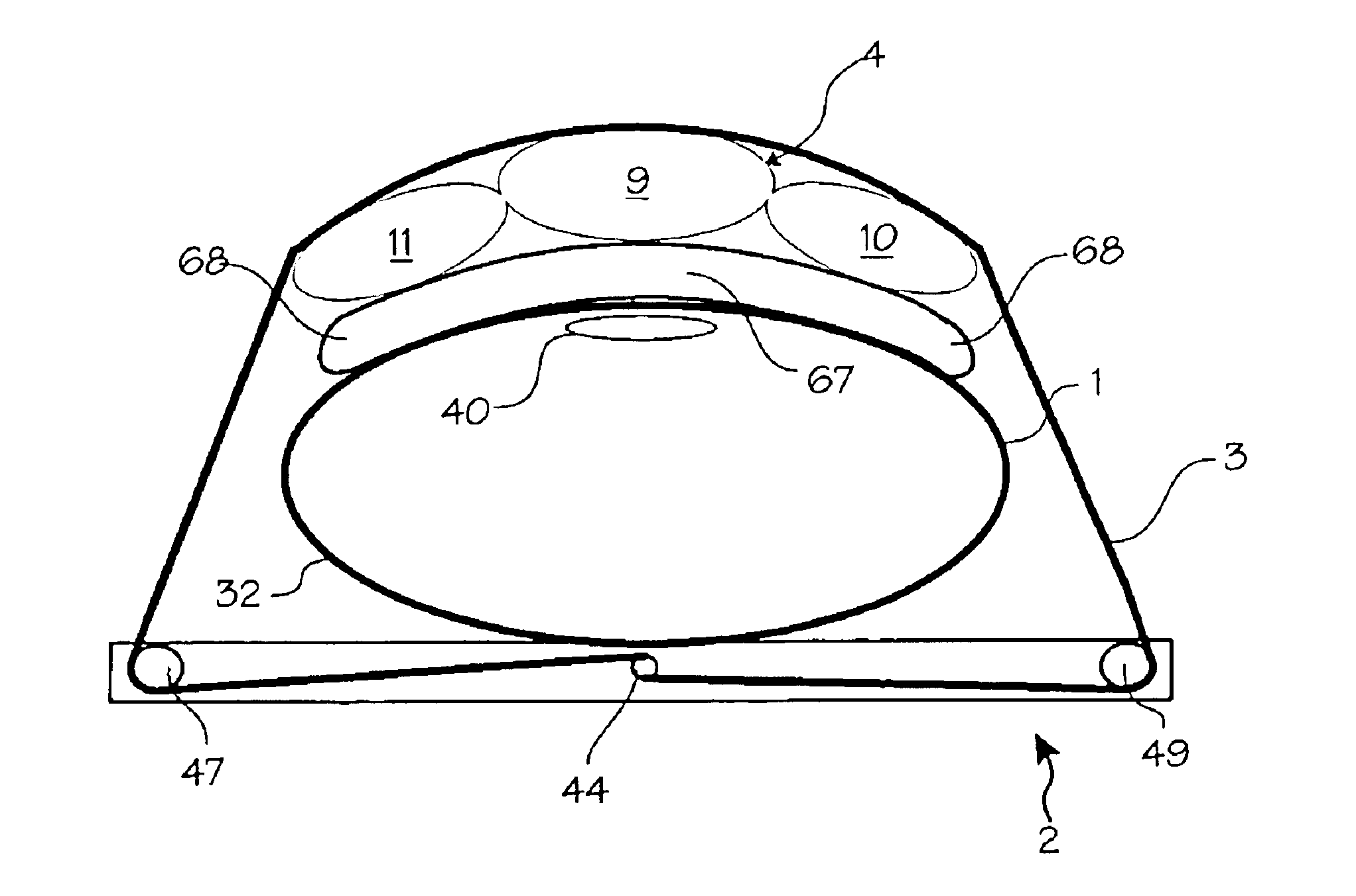
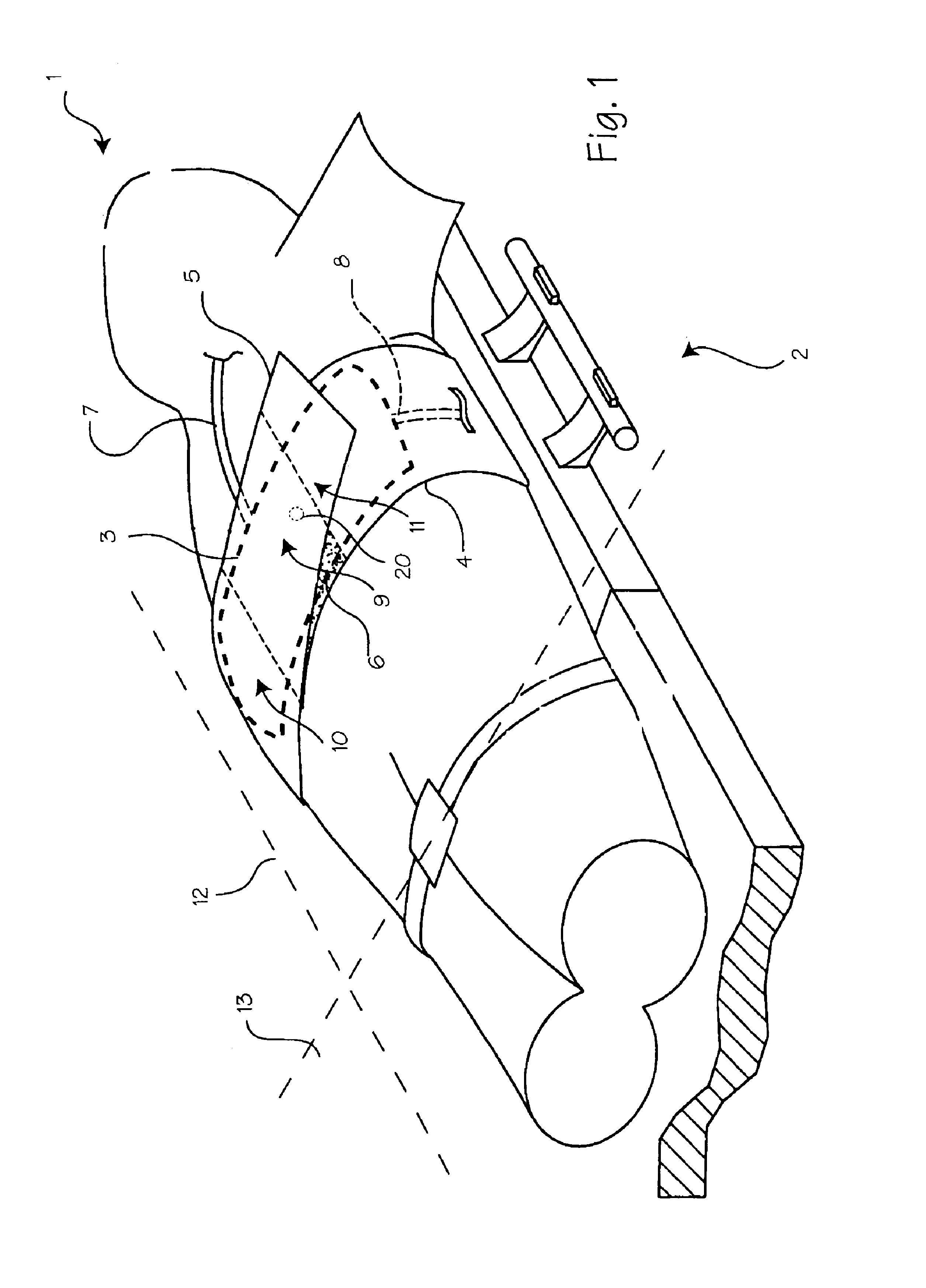
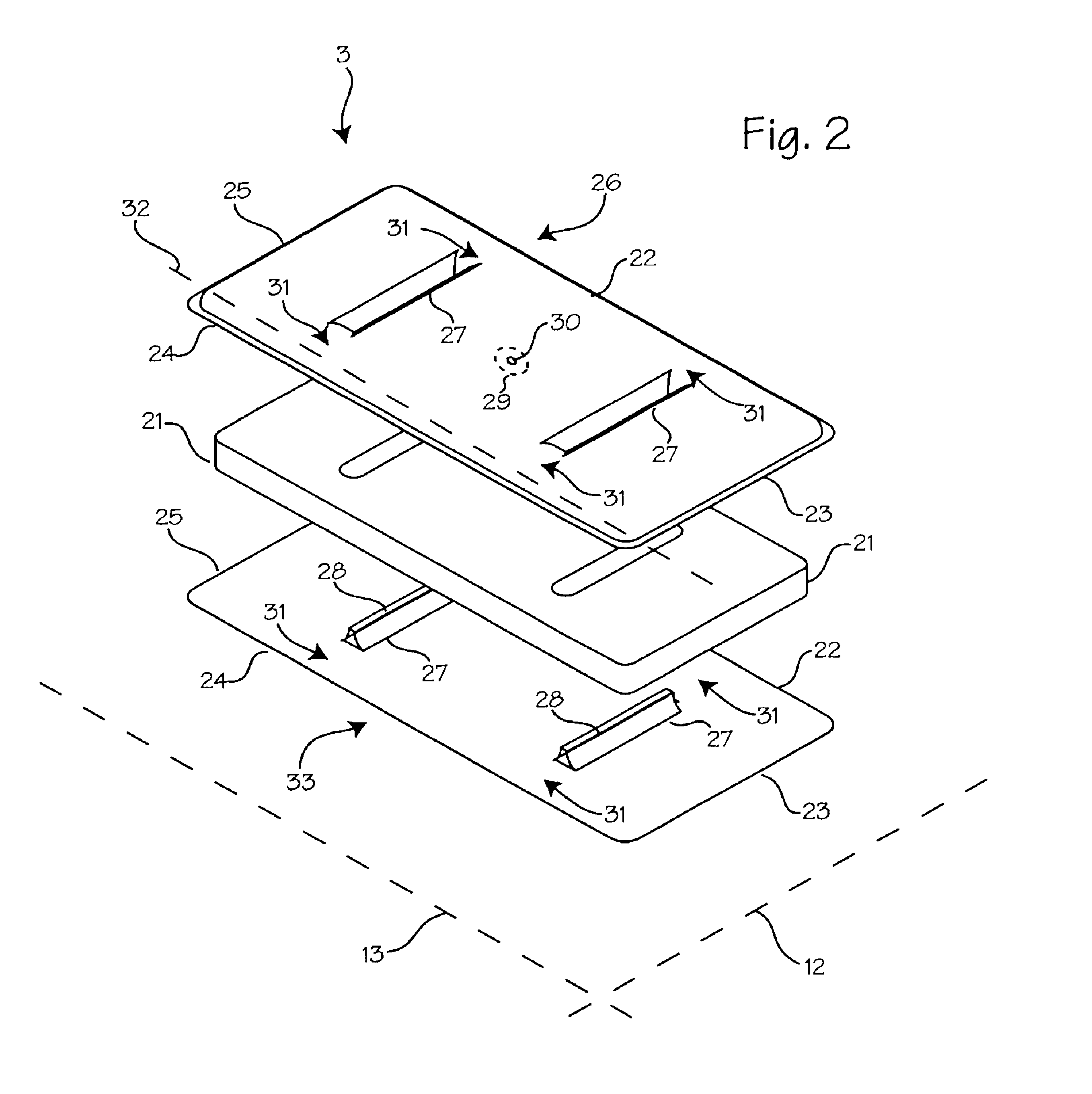
[0021]FIG. 1 illustrates a patient 1 with a chest compression device 2 fitted on the patient and ready for use. A belt 3 and a belt tightening mechanism within the backboard comprises the means for compressing the chest of the patient. The belt is operably connected to the belt tightening mechanism, which provides the force necessary to tighten the belt about the patient's chest and thorax. The belt tightening mechanism may be a motor and motor driven spool as shown in co-pending application Ser. No. 09 / 866,377, other automatic means for tightening the belt, or a pull-lever or other manual means for tightening the belt.

[0022]A bladder 4 is disposed between the patients chest and the compression belt. The bladder 4, shown in phantom to indicate its position below the belt, is secured to the belt 3. In turn, the belt is secured to the body with two overlapping areas 5 and 6 of hook and loop fastener, Velcro®, or other fastener. The bladder 4 may be provided with a sensing line 7 which...


PUM


Abstract

Improved automatic chest compression systems which use constricting belts, repeatedly inflating bladders, or reciprocating pistons to compress the chest. A bladder is placed between the chest and the particular mechanism used to compress the chest during CPR. The bladder maximizes the effectiveness of chest compressions.

Description

[0001]This application is a continuation-in-part of application Ser. No. 09 / 866,377 filed May 25, 2001 now U.S. Pat. No. 6,616,620.FIELD OF THE INVENTION[0002]This invention relates to emergency medical devices and methods and the resuscitation of cardiac arrest patients.BACKGROUND OF THE INVENTION[0003]Current American Heart Association guidelines call for chest compressions during cardio-pulmonary resuscitation (CPR) to be performed at a rate of 80 to 100 per minute and at a depth of 1.5 inches to 2.0 inches. (Guidelines 2000 for Cardiopulmonary Resuscitation and Emergency Cardiovascular Care, 102 Circulation Supp. I (2000).) When a first aid provider performs CPR according to these guidelines, blood flow in the body is about 25 to 30% of normal. However, when chest compressions are required for long periods of time it is difficult, if not impossible, to maintain adequate compression of the heart and rib cage. Even experienced paramedics cannot maintain adequate chest compressions...

Claims


Application Information

Patent Timeline
Patent Type & Authority Patents(United States)
IPC IPC(8): A61H31/00A61N1/39A61B
CPCA61H9/0078A61H31/00A61H31/005A61H31/006A61H31/008A61N1/3968A61H2011/005A61H2031/003A61H2201/0103A61H2201/0173A61H2201/0176A61H2201/018A61H2201/1238A61H2201/165A61H2201/5007A61H2201/501A61H2201/5012A61H2201/5043A61H2201/5058A61H2201/5061A61H2201/5064A61H2201/5071A61H2201/5089A61H2201/5097A61H2230/04A61H2230/207A61H2230/30A61M16/00A61M16/10A61M2205/3546A61N1/046A61N1/39Y10S601/07A61N1/39044
Inventor HALL, GREGORY W.JENSEN, JAMES O.ESCUDERO, PAULSHERMAN, DARREN R.KATZ, BOB
Owner ZOLL CIRCULATION
Why Eureka
Try Eureka