
Medical device including tube having a braid and an expanded coil

Inactive Publication Date: 2005-09-06
COOK MEDICAL TECH LLC
View PDF23 Cites 175 Cited by
  • Summary
  • Abstract
  • Description
  • Claims
  • Application Information

AI Technical Summary

Benefits of technology

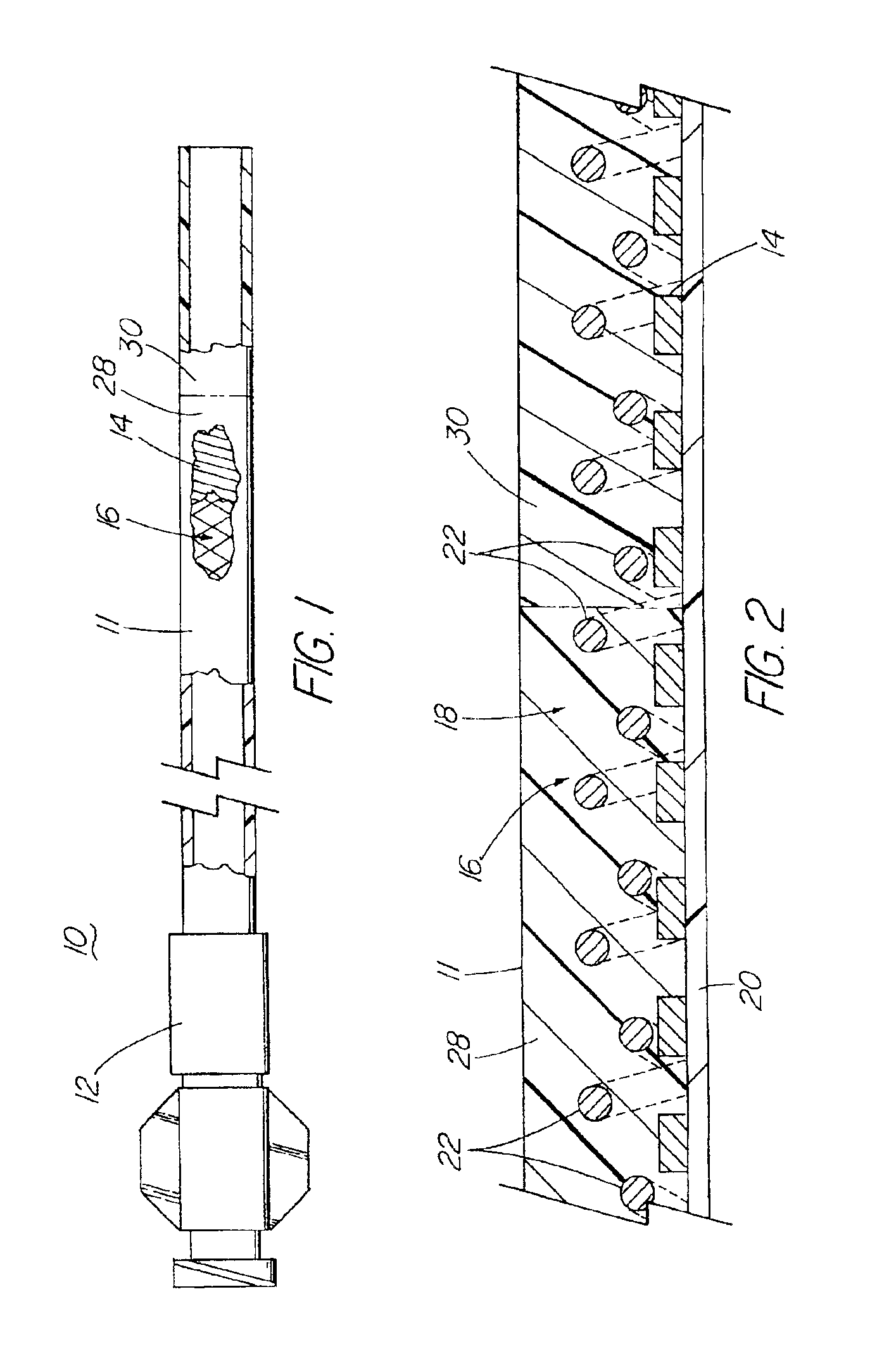
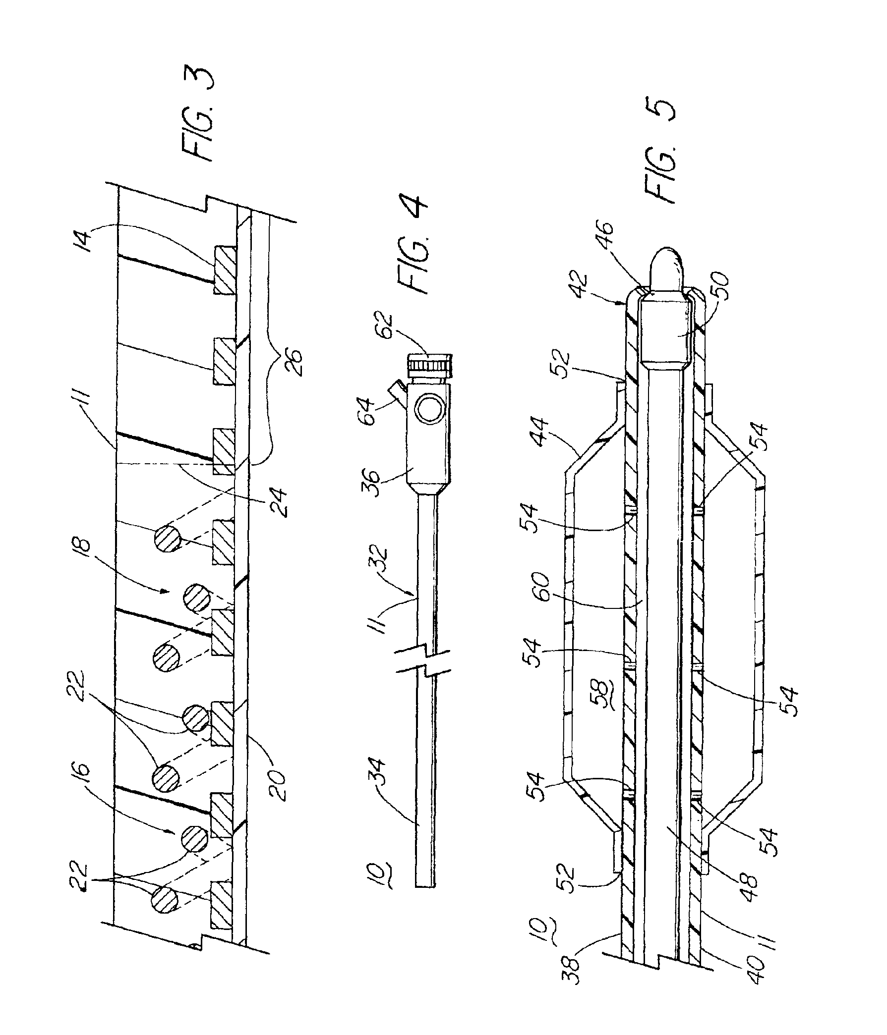
[0011]The foregoing problems are solved and a technical advance is achieved in an illustrative medical device for performing any of a variety of minimally invasive medical procedures, including angioplasty, diagnosis, chemotherapy, drainage, endoscopy, laparoscopy, arthroscopy, and the guiding or introduction of other devices into a patient. More particularly, the present invention is directed to a medical device which comprises a tube having a highly uniform and repeatable inner and outer diameter, the tube possessing good trackability, pushability and torquability, and the tube being highly resistant to collapse, necking or kinking during use. The tube first comprises a coil in a stressed, radially expanded condition, and a braid extending over at least part of the coil. The tube further comprises a polymeric bonding layer positioned over and contacting at least the coil. The polymeric layer itself maintains the coil in its stressed, radially expanded condition. The polymeric layer performs this function, for example, by adhesion to the coil (such as by thermally bonding to it). The tube may optionally include an inner liner beneath and in contact with at least part of the coil. However, particularly in smaller diameter constructions, the inner liner is by itself much too weak to prevent the coil from returning to its unstressed, non-expanded condition. While the polymeric layer has been described as being applied in tubular form over the coil, it could alternatively be extruded over and inside the coil to also form the inner liner 20. The layer 18 and line 20 could add further stability tot he tube. Polymerization could be accomplished in situ.
[0016]At least one and preferably both of the coil and the braid comprise a medical grade metal. The coil preferably comprises flat wire, while the braid may comprise a plurality of crossed wires that may be of flat or circular cross-section. The polymeric layer preferably comprises at least one of nylon and polyurethane; during manufacture a sleeve of FEP heat-shrinkable tubing (heat fused shrink tubing) may be utilized that is stripped after manufacture. The polymeric layer can comprise two or more discrete longitudinal segments of differing durometer. This provides the resulting tube with differing stiffness at those segments, allowing selection of the flexibility of the tip of the tube. Selective flexibility of the tip of the tube can also be achieved by allowing the coil to extend distally beyond the braid.
[0020]As indicated above, the medical device of the present invention possesses significant advantages over prior devices. The tube incorporated in medical devices according to the present invention is highly resistant to collapse, necking and kinking during use, and possesses good trackability, pushability and torquability during use. The tube can possess an outer diameter at or below about 1 mm, making it possible for medical devices according to the present invention to access sites deeper within a patient with decreased potential for trauma to the patient. Moreover, the present invention enjoys significant advantages during manufacture, having a highly uniform and repeatable inner and outer diameter even in micro-sizes (at or below about 1 mm outer diameter).

Problems solved by technology

However, particularly in smaller diameter constructions, the inner liner is by itself much too weak to prevent the coil from returning to its unstressed, non-expanded condition.

Method used


Image

  • Medical device including tube having a braid and an expanded coil
  • Medical device including tube having a braid and an expanded coil
  • Medical device including tube having a braid and an expanded coil

Examples


Embodiment Construction

[0027]With reference to FIGS. 1 and 2, a first embodiment of a medical device 10 according to the present invention is thereshown, useful for performing any of a variety of minimally invasive medical procedures, including angioplasty, diagnosis, chemotherapy, drainage, endoscopy, laparoscopy, arthroscopy, and the guiding or introduction of other devices into a patient. In its simplest form, the medical device 10 is a simple diagnostic, infusion or drainage catheter 12. The catheter 12 should be considered to also represent a guide catheter or an introducer sheath.

[0028]The medical device of the present invention comprises a tube 11. The tube 11 may be up to about 2 to about 3 French (about 0.67 to about 1.00 mm) in outer diameter, and may be as small as about 1.5 French (0.50 mm) or less, in outer diameter. The tube 11 first comprises a coil 14 in a stressed, radially expanded condition. The coil 14 is preferably formed of a flat wire comprised of a medical grade metal. The tube 11 ...


PUM


Abstract

A medical device (10) including a tube (11) having a highly uniform and repeatable inner and outer diameter, the tube (11) possessing good trackability, pushability and torquability, and the tube (11) being highly resistant to collapse, necking or kinking during use. The tube (11) first includes a metal coil (14) in a stressed, radially expanded condition, the metal coil (14) preferably being formed as a flat wire. The tube (11) also includes a metal braid (16) extending over at least part of the coil (14). The tube (11) further includes a polymeric bonding layer (18) positioned over and contacting at least the coil (14). The polymeric layer (18) is preferably heat-shrinkable shrinkable tubing made of one or more of nylon or polyurethane. The tube (11) optionally includes an inner liner (20) beneath and in contact with at least part of the coil (14), the liner (20) preferably being composed of PTFE. The polymeric layer (18) maintains the coil (14) in its stressed, radially expanded condition, for example, by adhesion to the coil (14) (such as by thermal bonding to it).

Description

RELATED APPLICATION[0001]This application claims priority from U.S. Provisional Application Ser. No. 60 / 218,203 filed Jul. 14, 2000.TECHNICAL FIELD[0002]This invention relates generally to medical devices and, more particularly, to devices for expanding a narrowed or obstructed passage or lumen in a patient, or for introducing a medication or catheter therethrough and into a patient, or to a sheath for maintaining access to the vascular system of a patient.BACKGROUND OF THE INVENTION[0003]Perhaps one of the most important advances in surgery over the last few decades has been the adoption and routine performance of a variety of minimally invasive procedures. Examples of minimally invasive procedures include angioplasty, endoscopy, laparoscopy, arthroscopy and the like. Minimally invasive surgical procedures such as these can be distinguished from conventional open surgical procedures in that access to a site of concern within a patient is achieved through a relatively small incision...

Claims


Application Information

Patent Timeline
IPC IPC(8): A61L29/00A61L29/02A61L29/04A61L29/12A61M25/00A61F2/958A61B1/00A61M25/16
CPCA61L29/02A61L29/04A61L29/126A61M25/0053A61M25/0054A61M2025/0079A61M25/00
Inventor PARKER, FRED T.OSBORNE, THOMAS A.
Owner COOK MEDICAL TECH LLC
Learn More