
Two-color photo-detector and methods for demosaicing a two-color photo-detector array

a two-color photo-detector and array technology, applied in the field of digital color image sensors, can solve the problems of high cost of prism and optics, inconvenient imager applications, and inability to produce two-color photo-detector arrays, so as to improve the dynamic range of each photo-detector element, reduce the area for producing two-color photo-detectors, and improve the effect of color separation

Inactive Publication Date: 2005-09-06
APTINA IMAGING CORP
View PDF15 Cites 18 Cited by
  • Summary
  • Abstract
  • Description
  • Claims
  • Application Information

AI Technical Summary

Benefits of technology

"The present invention provides a sensor with a two-color photo-detector that can sample more than one color at each photo-detector location. The sensor can use different thicknesses for the upper photo-detector elements of adjacent two-color photo-detectors to accurately sample color without a color filter array. A color-conversion matrix can be used to convert the four colors to a new color space, such as YCbCr (4:1:1.) The two photo-detector elements are electrically isolated from each other, improving the dynamic range and color separation between them. The invention also reduces the area for producing the two-color photo-detector and provides other features and advantages."

Problems solved by technology

Demosaiced images frequently exhibit color aliasing artifacts (distortion) due to the inherent under-sampling of color on an image sensor fitted with a CFA.
However, the cost of the prism and optics is extremely high.
In addition, the need to manually align, in both X and Y, the three sensors and optics to less than a fraction of the width of a photo-detector, which is on the order of 3 microns, is prohibitive for many imager applications.
Therefore, in order to measure the differences in current coming out of all three photodiodes, a significant amount of extra circuitry is required, which can be both cost prohibitive and area prohibitive.
Although the Findlater design provides more accurate color reconstruction as compared to the conventional “Bayer” pattern, the color separation of the two bulk photodiodes is poor, since the absorption spectrum (i.e., sensitivity regions) of each of the sensors is fixed.
In addition, with the Findlater design, the photo-detector itself is large due to the fact that two photodiodes and all of the circuitry for each photo-detector are integrated into the bulk silicon, adding both area and cost.

Method used


Image

  • Two-color photo-detector and methods for demosaicing a two-color photo-detector array
  • Two-color photo-detector and methods for demosaicing a two-color photo-detector array
  • Two-color photo-detector and methods for demosaicing a two-color photo-detector array

Examples


Embodiment Construction

[0023]The numerous innovative teachings of the present application will be described with particular reference to the exemplary embodiments. However, it should be understood that these embodiments provide only a few examples of the many advantageous uses of the innovative teachings herein. In general, statements made in the specification do not necessarily delimit any of the various claimed inventions. Moreover, some statements may apply to some inventive features, but not to others.

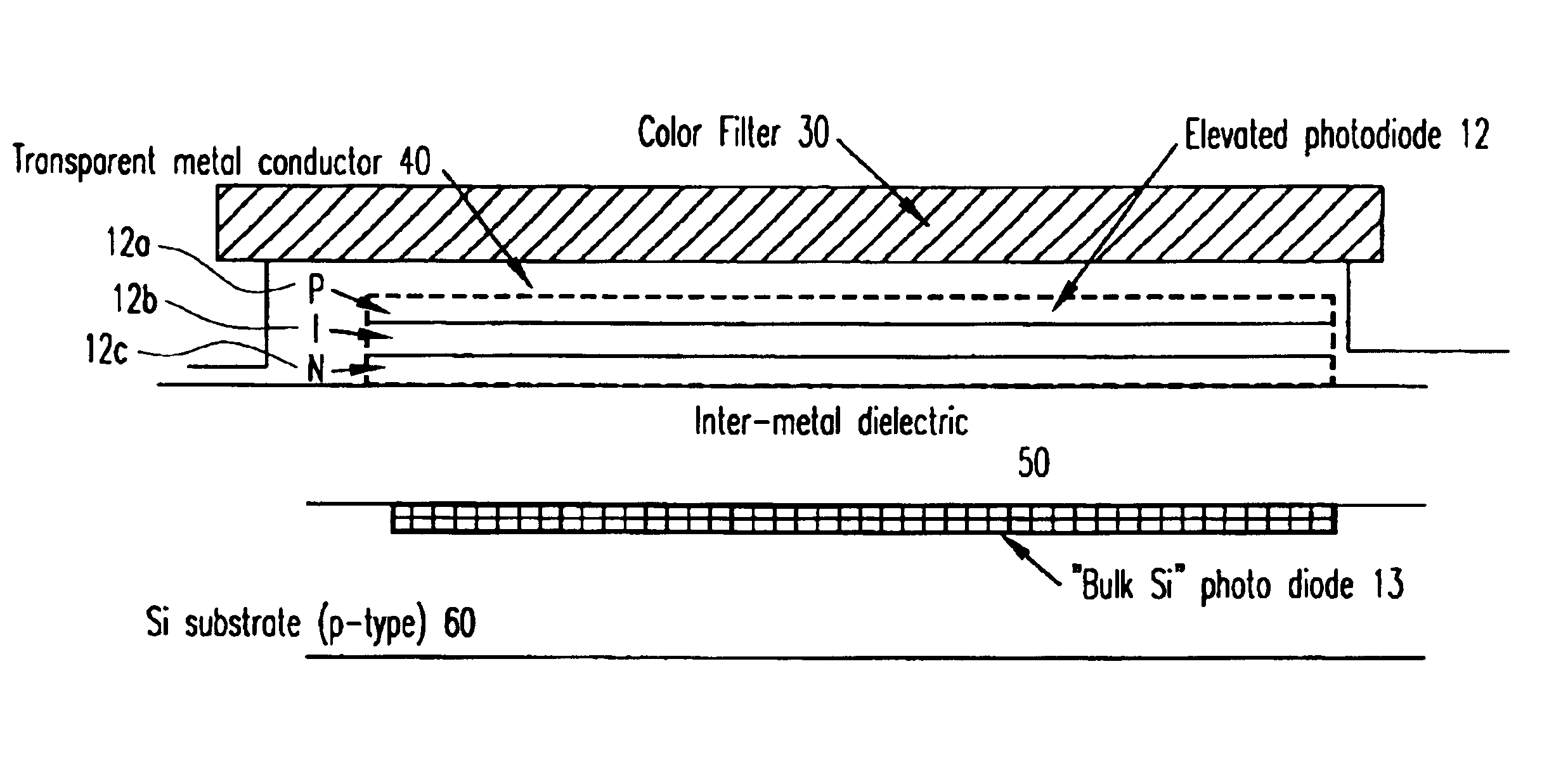
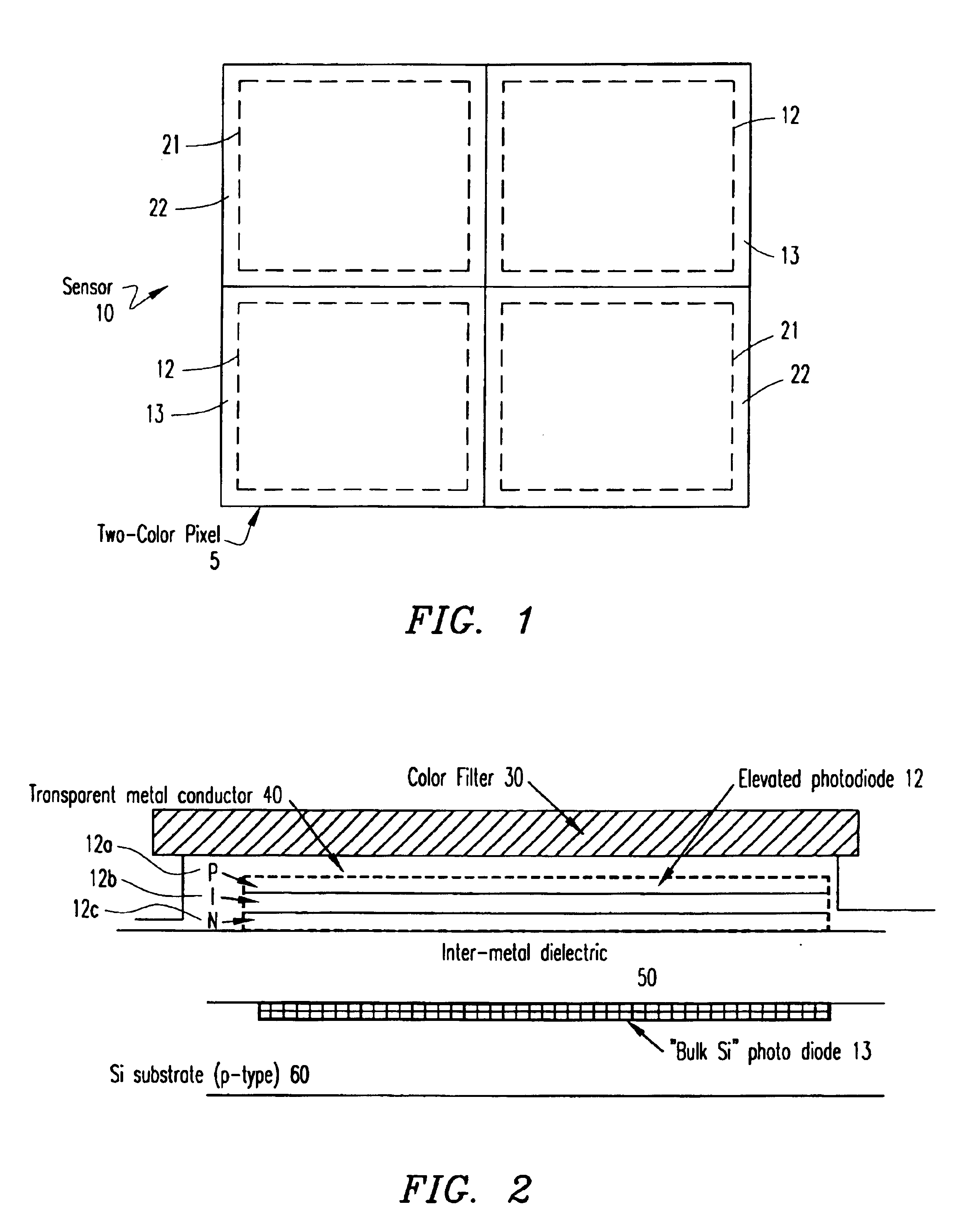
[0024]FIG. 1 illustrates an exemplary 2×2 block of two-color photo-detectors 5 (e.g., pixels) for a digital image sensor 10. In FIG. 2, within the area of four photo-detectors are eight photo-detector elements (i.e., photodiodes, photo-conductors or photo-transistors). Each of the photo-detectors is a two-color photo-detector 5 having two photo-detector elements, each detecting a different color. Within the 2×2 block of two-color photo-detectors 5, there are two types of two-color photo-detectors. One ty...


PUM


Abstract

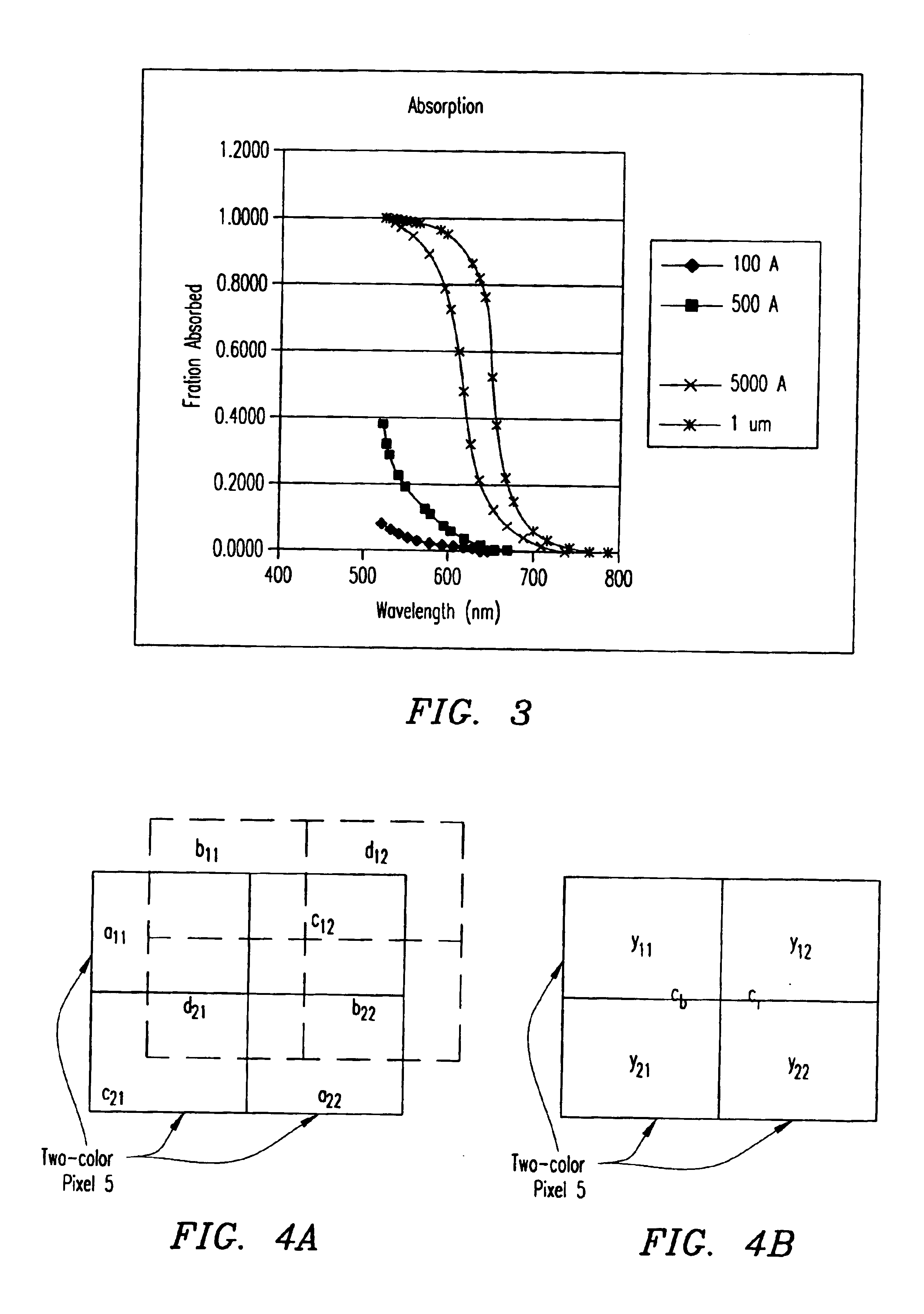
A two-color photo-detector capable of sensing two colors at a single photo-detector location is provided having a lower photo-detector element resident in the bulk silicon and an upper photo-detector element elevated above the lower photo-detector element. The color sensitivity of each of the photo-detector elements is determined according to the absorption curve of the upper photo-detector element, the thickness of the upper photo-detector element and the color filter array, if any. The elevated upper photo-detector element overlies the circuitry needed for both the upper photo-detector element and the lower photo-detector element. In order to accurately sample color within an array of two-color photo-detectors without a color filter array, two different thicknesses for the upper photo-detector elements of adjacent two-color photo-detectors are used. Therefore, each pair of two-color photo-detectors within the array senses four different colors (i.e., blue and the complement of blue and red and the complement of red). To process the raw color values for compression and storage, a simple color-conversion matrix can be used on a 2×2 block of two-color photo-detectors to convert the four colors (eight color values) to a new color space, such as YCbCr (4:1:1), without traditional demosaicing neighborhood operations.

Description

BACKGROUND OF THE INVENTION[0001]1. Technical Field of the Invention[0002]The present invention relates generally to digital color image sensors, and specifically to a two-color photo-detector capable of detecting two colors at a single photo-detector location and a method for demosaicing a two-color photo-detector array.[0003]2. Description of Related Art[0004]Digital color image sensors are predominately of two types: CCDs (Charge Coupled Devices) and CMOS—APS (Complimentary Metal Oxide Semiconductor—Active Photo-detector Sensors). Both types of sensors typically contain an array of photo-detectors (e.g., pixels), arranged in rows and columns or arranged in other patterns, that sample color within an image. Each photo-detector measures the intensity of light within one or more ranges of wavelengths, corresponding to one or more perceived colors.[0005]In addition, both types of sensors may include a color filter array (CFA), such as the CFA described in U.S. Pat. No. 3,971,065 to B...

Claims


Application Information

Patent Timeline
Patent Type & Authority Patents(United States)
IPC IPC(8): H01L27/146H01L31/10H04N23/12H04N25/00
CPCH01L27/14621H01L27/14645H04N9/045H04N2209/046H04N2209/047H04N23/843H04N25/17
Inventor BAHARAV, IZHAKLONGERE, PHILIPPEVOOK, DIETRICH W.
Owner APTINA IMAGING CORP
Learn More