Near field probe

a near field and probe technology, applied in the direction of instruments, electric devices, measurement using dc-ac conversion, etc., can solve the problems of no longer being a manufacturer of the probe, the diode detector of the probe would fail, and the cost of replacement is high, so as to achieve high reliability

Inactive Publication Date: 2005-09-06
THE UNITED STATES OF AMERICA AS REPRESENTED BY THE SECRETARY OF THE NAVY
View PDF4 Cites 66 Cited by
  • Summary
  • Abstract
  • Description
  • Claims
  • Application Information

AI Technical Summary

Benefits of technology

[0006]The present invention overcomes some of the disadvantages of the prior art in that it comprises an inexpensive, highly reliable and very accurate near field probe for testing installed components of an electromagnetic radiating system on the SM-1 missile. The probe design comprises a dipole antenna with a balun. The probe utilizes a dual diode arrangement which provides approximately twice the output voltage as compared to the previous probe. The probe may then be placed further away from the antenna under test to achieve the same voltage output so that manufacturing tolerances are not critical. Since the output voltage is doubled, the previous probe's problem of providing a marginal voltage output is alleviated.

Problems solved by technology

The probe previously used to test the components of the radiating system for the SM-1 missile had serious reliability problems in that the probe's diode detectors would fail and were very expensive to replace.
Further, there is no longer a manufacturer for the probe, necessitating a more reliable but less costly replacement for the probe.

Method used


Image

  • Near field probe
  • Near field probe
  • Near field probe

Examples


Embodiment Construction

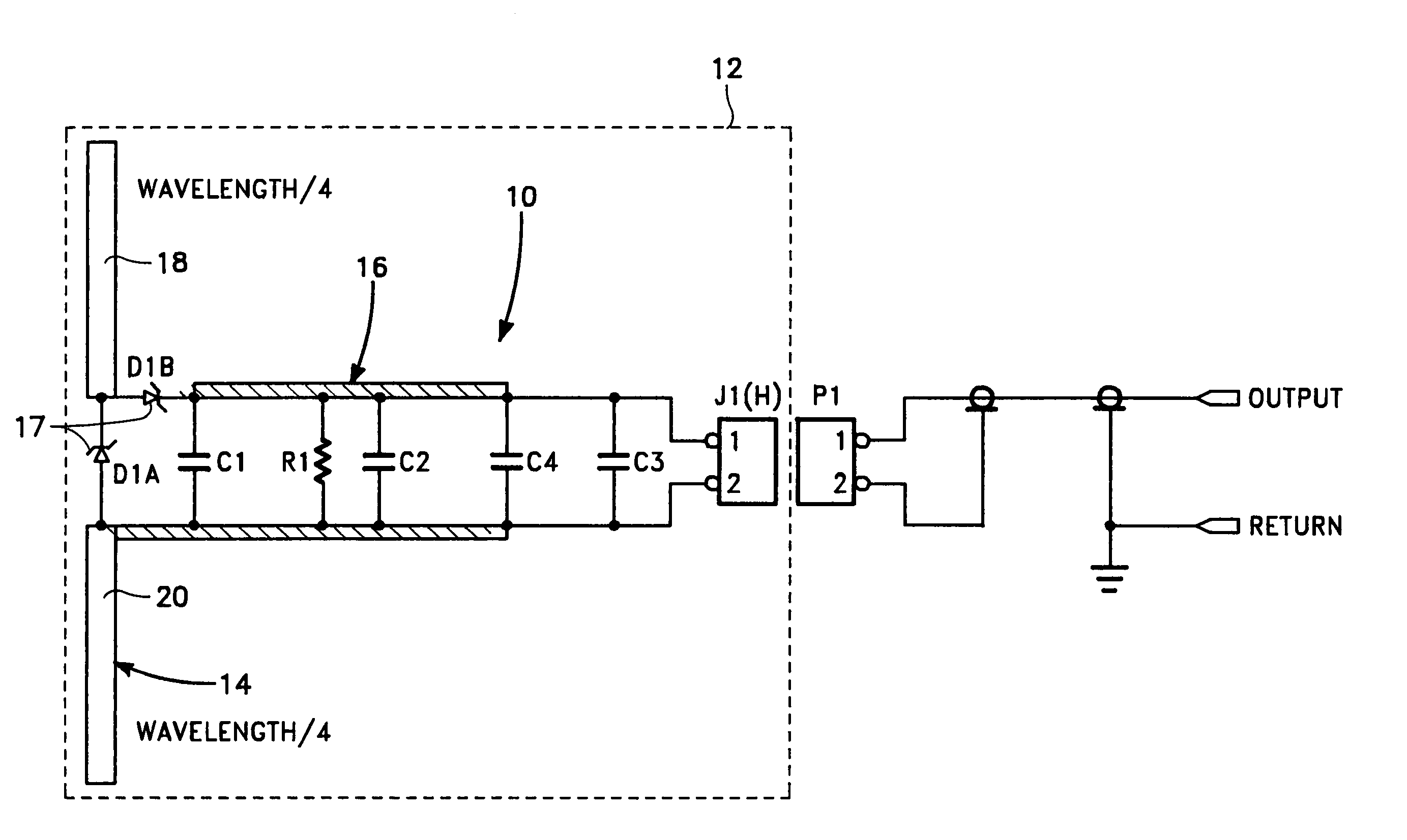
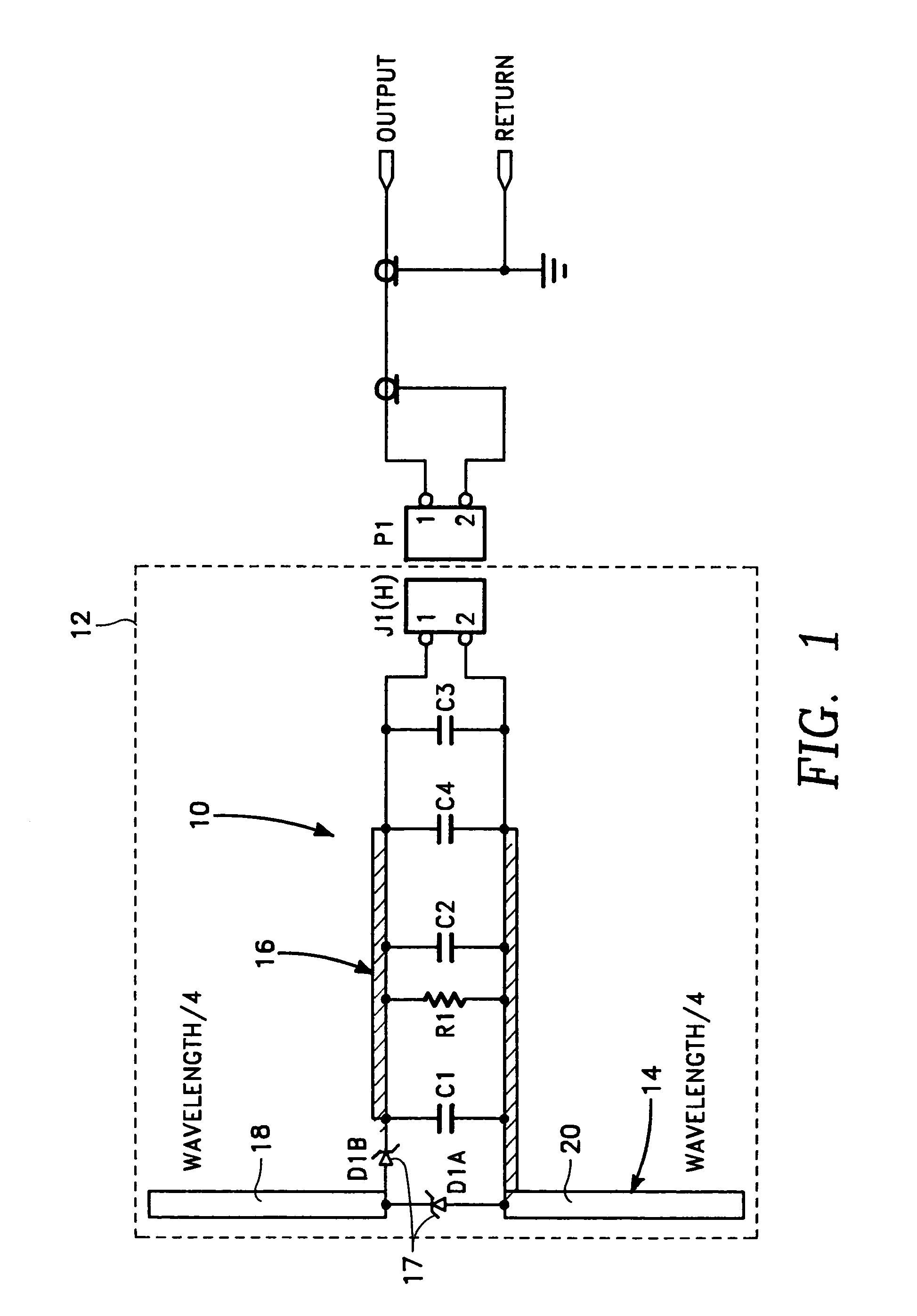
[0012]Referring first to FIGS. 1, and 3, there is shown a near field probe, designated generally by the reference numeral 10, for testing installed components of an electromagnetic radiating system on the SM-1 missile. The near field probe is mounted on microstrip printed circuit board 12.

[0013]The near field probe 10 includes a dipole antenna 14 having a balun 16. Balun 16, which is a transmission line transformer, is connected to header connector J1(H) of circuit board 12, pins 1 and 2, as shown in FIG. 1. Header connector J1(H) allows for ease of installation and removal of the antenna 14 of near field probe 10.

[0014]A diode detector 17 consisting of a pair of Schottky diodes D1A and D1B is integrated into near filed probe 10. The anode of diode D1A is connected to antenna element / dipole 20 of dipole antenna 14 and the cathode of diode D1A is connected to antenna element / dipole 18 of dipole antenna 14. The anode of diode D1B is connected to antenna element 18 of dipole antenna 14...


PUM


Abstract

A near field probe for testing installed components of an electromagnetic radiating system on a missile. The probe design comprises a diode antenna with a balun. The probe utilizes a dual diode arrangement which provides approximately twice the output voltage as the previous probe. The probe may then be placed further away from the radiating system under test.

Description

BACKGROUND OF THE INVENTION[0001]1. Field of the Invention[0002]The present invention relates generally to a probe for testing components of an electromagnetic radiating system. More specifically, the present invention relates to a near field probe in an antenna coupler that is designed to test installed components of an electromagnetic radiating system by coupling from the system to perform the test.[0003]2. Description of the Prior Art[0004]There is currently a need for a near field probe for use in testing installed components of an electromagnetic radiating system on the SM-1 missile. Specifically, the probe should be designed to provide an accurate voltage response as a function of frequency for the radiating system on the SM-1 missile when the probe is positioned in the SM-1 DC coupler.[0005]The probe previously used to test the components of the radiating system for the SM-1 missile had serious reliability problems in that the probe's diode detectors would fail and were very ...

Claims


Application Information

Patent Timeline
Patent Type & Authority Patents(United States)
IPC IPC(8): G01R23/04G01R23/00G01R27/02G01R21/12G01R29/08
CPCG01R21/12G01R29/0878
Inventor RYKEN, JR., MARVIN L.DAVIS, ALBERT F.
Owner THE UNITED STATES OF AMERICA AS REPRESENTED BY THE SECRETARY OF THE NAVY
Why Eureka
Try Eureka