Coil filter and method for manufacturing the same

a technology of coil filter and coil core, which is applied in the direction of inductance with magnetic core, waveguide type devices, inductance, etc., can solve the problems of current capacity, shape and processing of soldered parts on both ends of the coil, and limit the operating frequency rang

Inactive Publication Date: 2005-09-06
KOMIYA KUNIFUMI
View PDF8 Cites 24 Cited by
  • Summary
  • Abstract
  • Description
  • Claims
  • Application Information

AI Technical Summary

Benefits of technology

[0020]Further, the end parts of the conducting wire are positioned on the inner side of the outermost circumferential part of the coil shape, such that the core material formed of magnetic material or the rod-shaped core disposed inside the coiled conducting wire does not fall out.

Problems solved by technology

However, the effects of packaging in these types of structures and the structure-related stray capacitance, parasitic capacitance, and the like lead to limitations in the operating frequency range, a deficiency in current capacity due to the large conducting resistance, or problems in magnetic saturation, Q-value, or insertion loss.
Further, for coils having the simple construction of a wound conducting wire, problems have occurred in the shape and processing of soldered parts on both ends of the coil that are used as terminals (electrodes) for connecting the coil to the circuit.
However, in tape and reels that accommodate plastic embossed areas, the edges of the cut surface of the conducting wire on the end portions of the coil can catch on the inner surface of the plastic embossed tape, causing a decrease in the yield rate.

Method used


Image

  • Coil filter and method for manufacturing the same
  • Coil filter and method for manufacturing the same
  • Coil filter and method for manufacturing the same

Examples


first embodiment

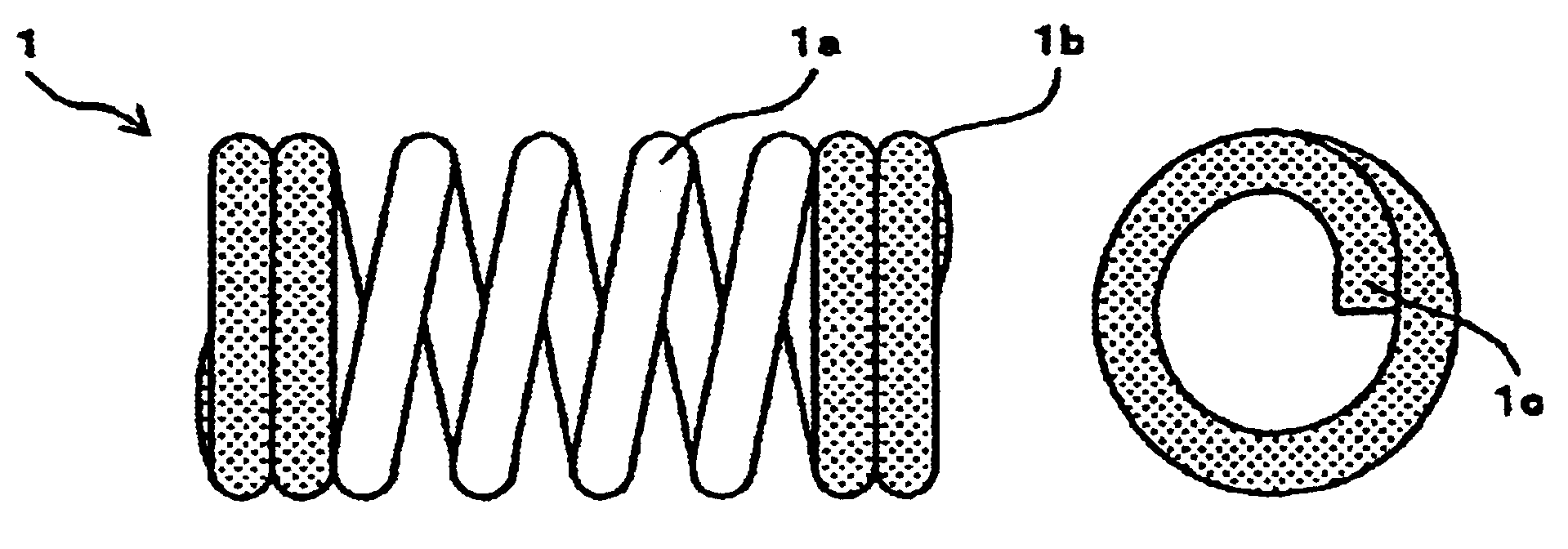
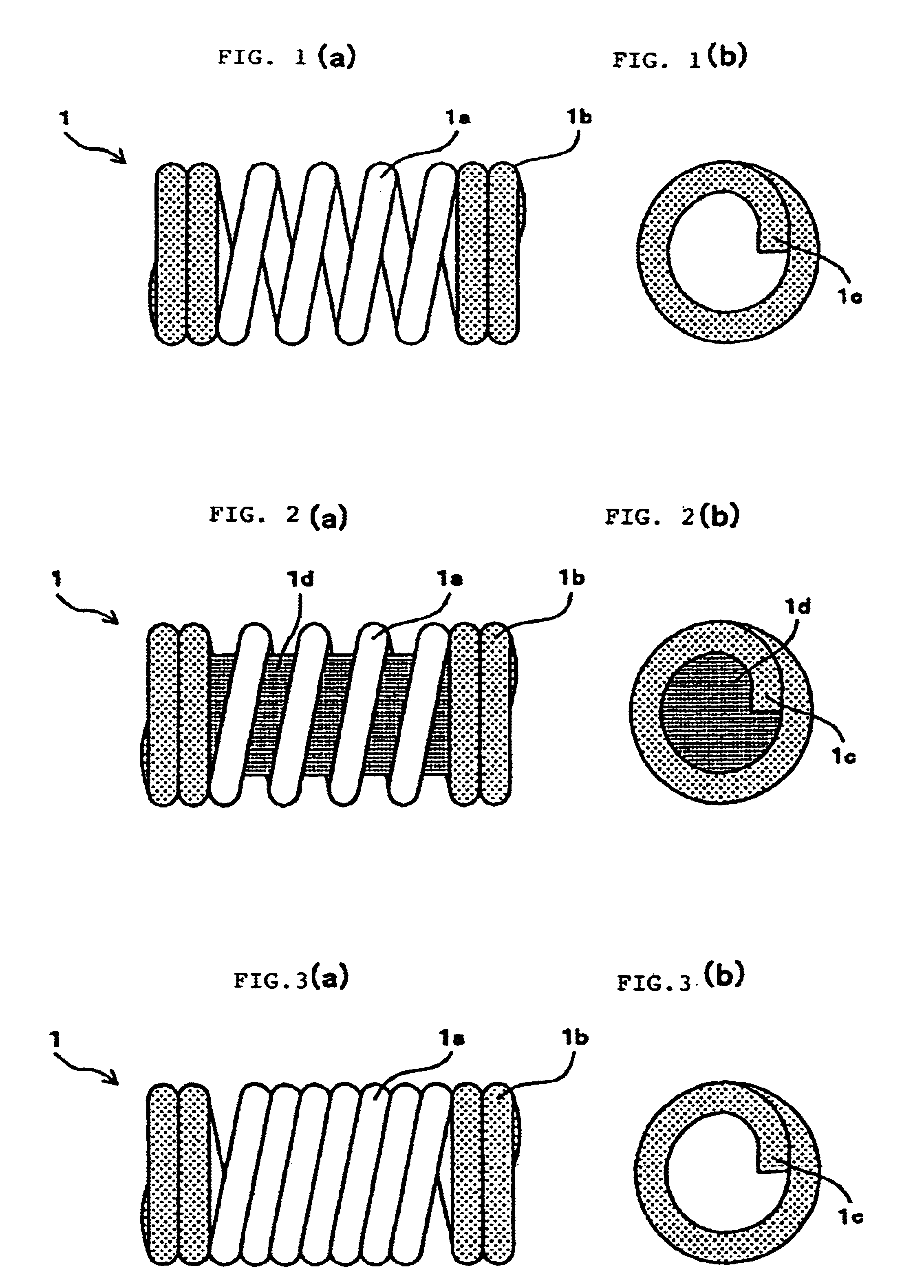
[0025]FIG. 1 (a) is a front view of the coil filer showing the share of a coil filter according to the present invention;

[0026]FIG. 1(b) is a side view of the coil filter;

[0027]FIG. 2(a) is a front view of the coil filter showing a core material inserted into the coil filter of FIG. 1;

[0028]FIG. 2(b) is a side view of the coil filter;

second embodiment

[0029]FIG. 3(a) is a front view of the coil filter showing the shape of a coil filter according to the present invention;

[0030]FIG. 3(b) is a side view of the coil filter;

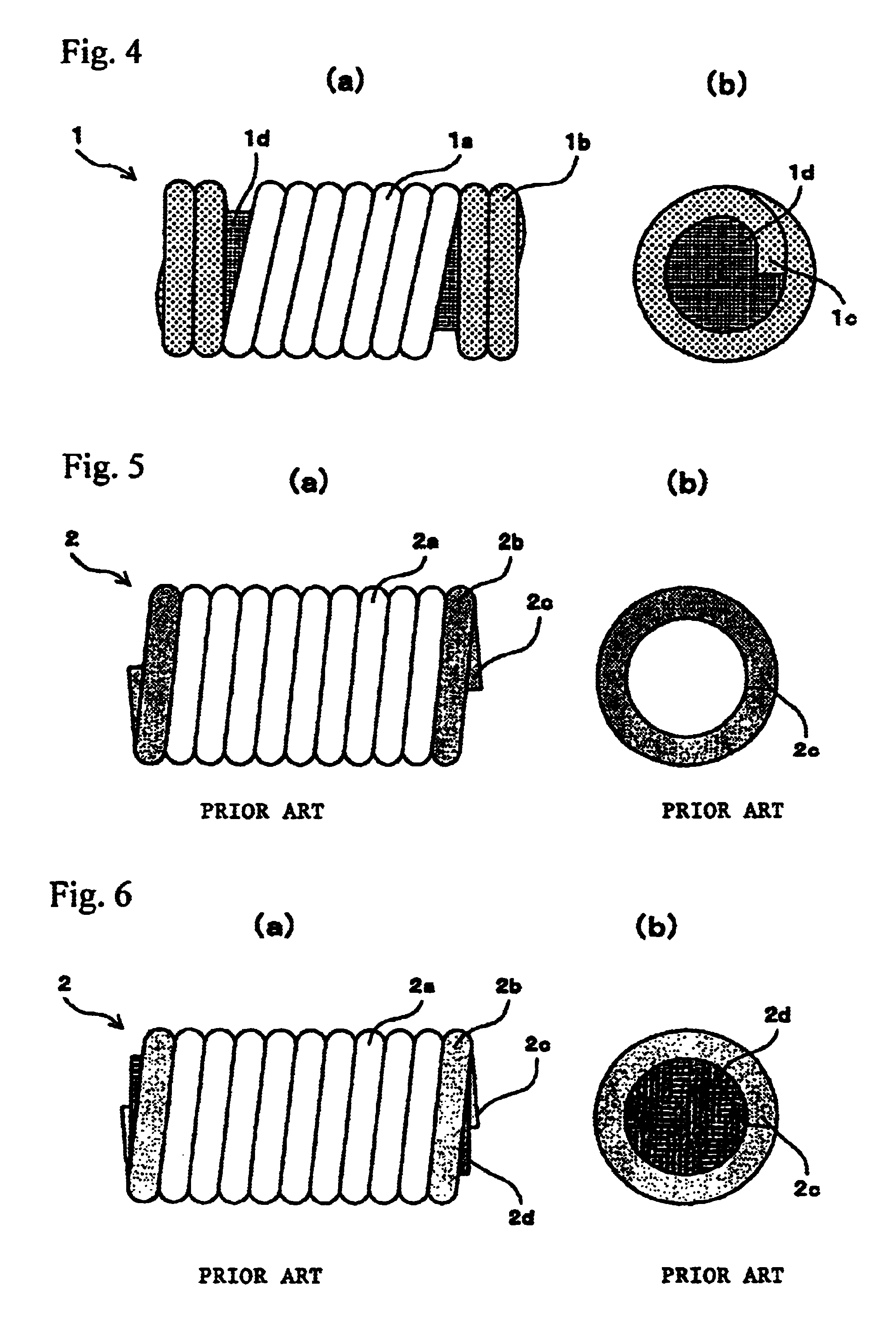
[0031]FIG. 4(a) is a front view of the coil filter showing a core material inserted into the coil filter of FIG. 3;

[0032]FIG. 4(b) is a side view of the coil filter;

[0033]FIG. 5(a) is a front view of the inductor showing the share of an inductor configured of a conventional air-core coil;

[0034]FIG. 5(b) is a side view of the inductor;

[0035]FIG. 6(a) is a front view showing the inductor showing the shave of an inductor configured of a conventional coil with an inserted core material;

[0036]FIG. 6(b) is a side view showing the inductor;

[0037]FIG. 7(a) shows the impedance characteristics of a common ferrite bead inductor showing the impedance characteristics of an inductor;

[0038]FIG. 7(b) shows the impedance characteristics of an air-core coil.

[0039]FIG. 8(a) is a graph showing the decay characteristics of a coil filte...


PUM

PropertyMeasurementUnit
frequencyaaaaaaaaaa
shapeaaaaaaaaaa
conductingaaaaaaaaaa

Abstract

The present invention provides a coil filter suitable for surface mounting on an electronic circuit board by automatic mounting and capable of realizing wide band isolation excellent in high-frequency characteristics without requiring consideration for the mutual position of parts. The coil filter functions to block electromagnetic waves or high-frequency signals propagating while being superimposed on a DC power supply, signal, or the like of an electronic apparatus such as an electronic circuit board. Conducting wires are bonded electrically at coil end parts such that a conducting wire part wound by one turn or more constitutes a short ring conducting in a ring shape on both sides of an intermediate part in which electrically insulated conducting wires are wound. End parts of the conducting wire are positioned on the inner side of the outermost circumferential part of the coil-shaped end faces.

Description

DETAILED DESCRIPTION OF THE INVENTION[0001]1. Field of the Invention[0002]The present invention relates to a coil filter that is surface-mounted on a circuit board in an electronic device for blocking electromagnetic waves, high-order harmonics, or high-frequency signals that become superimposed on and propagated along with a DC power supply, signals, or the like from the electronic device; and also to a method for manufacturing the coil filter.[0003]2. Description of the Related Art[0004]As electronic equipment has become lighter and more compact in recent years, progress has been made in miniaturizing parts used in the equipment and automatically mounting these small parts. Further, various chip-type inductors supporting surface mounting have been devised and are currently being used as inductor parts.[0005]These chip-type inductors include thick-film conductors formed on a ceramic or ferrite green sheet in a layered construction that are formed and fired, electrodes formed in a c...

Claims


Application Information

Patent Timeline
Patent Type & Authority Patents(United States)
IPC IPC(8): H01F27/29H01F17/04H01F17/02H01F27/00H03H7/01
CPCH01F17/045H01F27/292H01F17/02
Inventor KOMIYA, KUNIFUMI
Owner KOMIYA KUNIFUMI
Why Eureka
Try Eureka