Gate entry system using short range radio communications with user terminal devices

Inactive Publication Date: 2005-09-06
KK TOSHIBA
View PDF7 Cites 13 Cited by
  • Summary
  • Abstract
  • Description
  • Claims
  • Application Information

AI Technical Summary

Benefits of technology

[0012]It is therefore an object of the present invention to provide a gate entry system capable of carrying out the processing of the passengers properly at the automatic checking and collecting machine side, even when the Bluetooth is applied to the automatic checking and collecting machine, for example.

Problems solved by technology

However, in the conventional automatic checking and collecting machine, a ticket or pass conveyor section and a ticket or pass examination section have been expensive so that the price of the automatic checking and collecting machine itself has been very high.
Also, the conveyor section requires the fine-tuning and the maintenance cost due to its severe operating environment.
In addition, when the area for placing the automatic checking and collecting machine is limited, the automatic checking and collecting machine itself is so large that there has been a drawback that it is difficult to place many automatic checking and collecting machines.
Also, there has been an inconvenience that tickets usable for the automatic checking and collecting machine can be purchased only at limited places such as the railway station.
Compared with the contactless radio IC card, the Bluetooth has drawbacks in its long processing time and its weak security.
However, in the case of applying the Bluetooth to the automatic checking and collecting machine, there is a possibility for erroneously establishing the communication connection with the Bluetooth of the terminal device owned by a person other than the passenger who is currently trying to pass the automatic checking and collecting machine (such as a subsequent passenger, for example) and checking that other person's ticket rather than the passenger's ticket.
Also, when a plurality of passengers enter into the automatic checking and collecting machine consecutively, the communication data of the plurality of passengers will come into the radio wave reachable range of the Bluetooth on the automatic checking and collecting machine, such that it becomes impossible for the automatic checking and collecting machine side to check tickets in the correct order by which the passengers entered the automatic checking and collecting machine.

Method used


Image

  • Gate entry system using short range radio communications with user terminal devices
  • Gate entry system using short range radio communications with user terminal devices
  • Gate entry system using short range radio communications with user terminal devices

Examples


first modified embodiment

[0114

[0115]FIG. 8A shows the perspective view of the ticket gate device 1 according to the first modified embodiment. As shown in FIG. 8A, it is possible to provide the gate unit 3a near the entrance, in addition to the gate unit 3b near the exit. More specifically, when the first passenger 30 enters the ticket gate device 1, the gate unit 3a near the entrance is closed so as to block the entry of the subsequent passenger 30. Then, when the processing of the first passenger 30 in the ticket gate device 1 is finished and the first passenger 30 passes the ticket gate device 1, the gate unit 3a near the entrance is opened so as to permit the entry of the subsequent passenger 30.

[0116]According to the ticket gate device 1 of this first modified embodiment, it is possible to block the subsequent passenger 30 more definitely compared with the case of having only one gate unit 3.

second modified embodiment

[0117

[0118]FIG. 8B shows the perspective view of the ticket gate device 1 according to the second modified embodiment. As shown in FIG. 8B, it is possible to provide a speech unit 8 to the ticket gate device 1.

[0119]The speech unit 8 of this modified embodiment calls for the attention by the speech to the terminal device 10 carried by the passenger 30, and can be provided in a form of a loudspeaker for generating sounds, for example. Note that the speech unit 8 can be provided near the entrance of the ticket gate device 1.

[0120]The operation of the ticket gate device 1 in this configuration can be as follows. First, the user sets an own ID code (such as name, number, symbol, etc.) by using the operation unit 11 of the terminal device 10. Then, when the data containing the own ID code is transmitted from the terminal device 10 to the ticket gate device 1, the radio communication unit 5 receives that data.

[0121]Then, the data received by the radio communication unit 5 of the ticket ga...

third modified embodiment

[0123

[0124]FIG. 8C shows the perspective view of the ticket gate device 1 according to the third modified embodiment. As shown in FIG. 8C, the ticket gate device 1 may be provided with a shielding 9.

[0125]The shielding 9 of this modified embodiment shields the external noises, and can be provided in a form of a grounded conductor plate, for example. When the external noises are entered, this shielding 9 can shield the external noises by letting them go through the grounding of the conductor plate.

[0126]In this way, even when the data is transmitted to one ticket gate device 1 among a plurality of ticket gate devices, the similar data for the other ticket gate device 1 will not be mixed so that the data transmitted by the passenger 30 can be processed properly at the ticket gate device 1.


PUM


Abstract

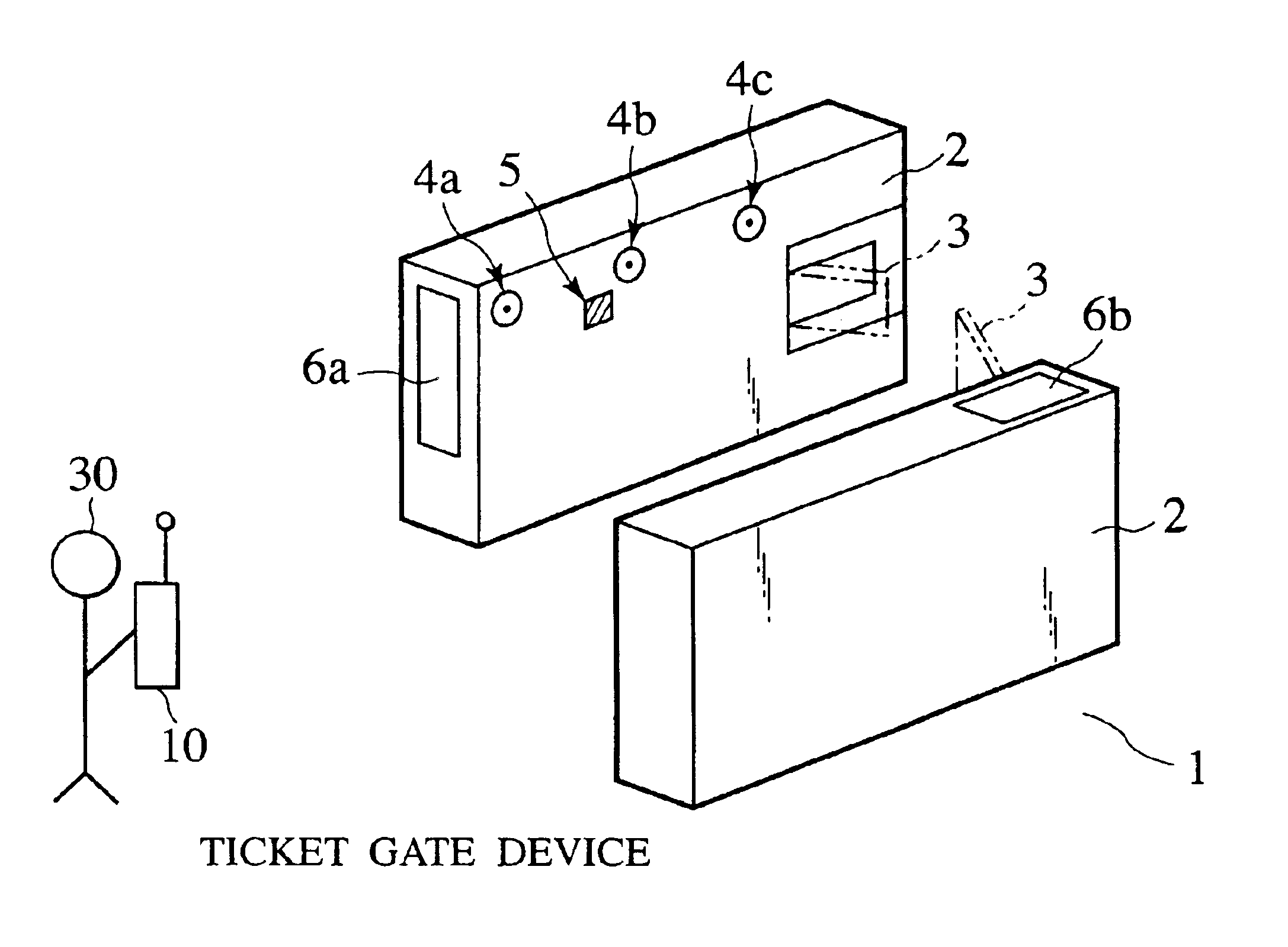
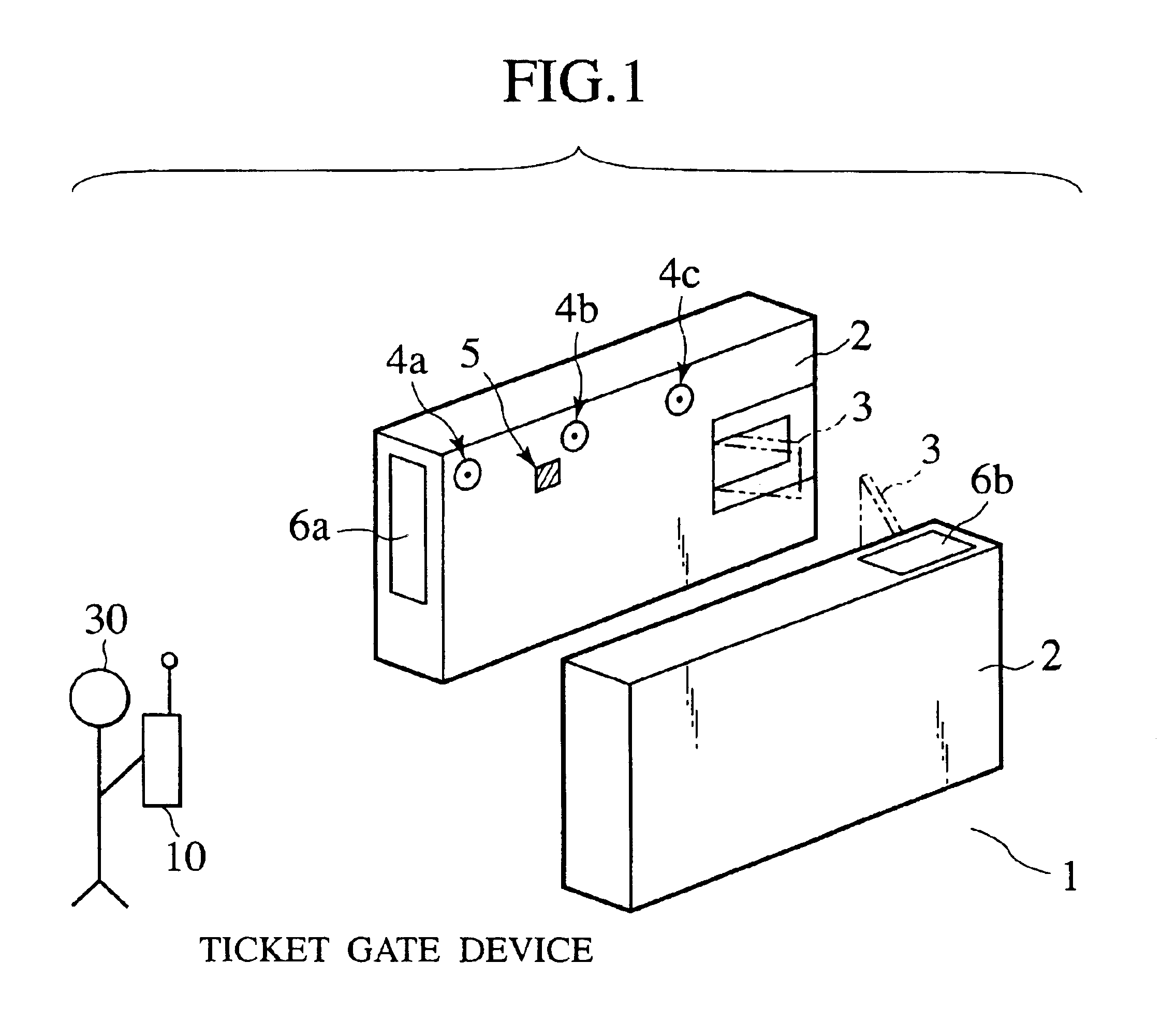
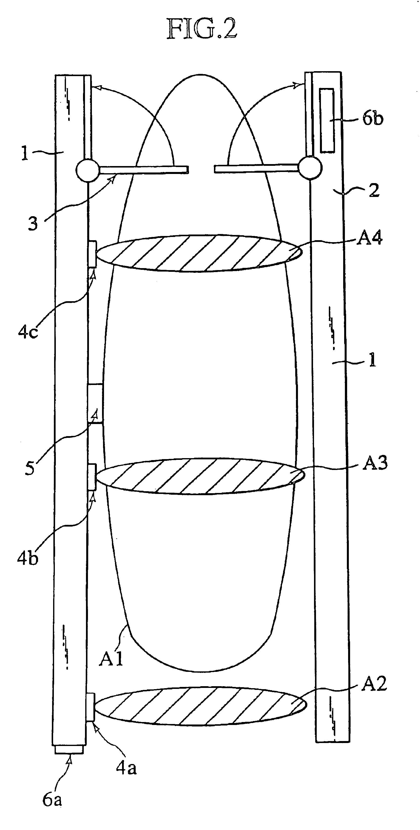
A gate entry system for regulating passages of passengers is formed by a wall unit for forming a passageway that is extended along a passing direction of the passengers, a gate unit provided at an exit side of the passageway, which is capable of being opened or closed to regulate the passages of the passengers, human sensors for sensing the passengers in the passageway, a radio communication unit for detecting a number of passengers entering into the passageway according to outputs of the human sensors, and carrying out transmission / reception of data with respect to at least one terminal device of one passenger, and a control unit for controlling opening or closing of the gate unit according to the data received by the radio communication unit.

Description

[0001]This application is a continuation of U.S. patent application Ser. No. 10 / 108,466, filed Mar. 29, 2002, now U.S. Pat. No. 6,744,369, the entire contents of which are hereby incorporated herein by reference.BACKGROUND OF THE INVENTION[0002]1. Field of the Invention[0003]The present invention relates to a gate entry system for regulating passages of passengers.[0004]2. Description of the Related Art[0005]As a conventional gate entry system for regulating passages of passengers, there is an automatic checking and collecting machine used at a railway station, for example. In order to pass the automatic checking and collecting machine, the user enters a commutation pass of the user into the automatic checking and collecting machine, and if the commutation pass is recognized as valid, the user can pass the automatic checking and collecting machine. For this reason, by the use of the automatic checking and collecting machine, it has been possible to comprehend users of the station ac...

Claims


Application Information

Patent Timeline
IPC IPC(8): G07B15/00G07C9/02G07C9/00G07B15/02H04B1/59H04B5/02
CPCG07B15/00G07C9/00G07C9/02G07C9/10
Inventor SATA, YUTAKA
Owner KK TOSHIBA
Why Eureka
Try Eureka