Dual head laser system with intra-cavity polarization, and particle image velocimetry system using same

a laser system and laser technology, applied in lasers, devices using optical means, instruments, etc., can solve the problems of complicated image analysis, complicated analysis of particle movement, etc., and achieve the effects of less cost, improved accuracy and improved accuracy

Inactive Publication Date: 2005-09-06
ELEMENTAL SCI LASERS LLC +1
View PDF10 Cites 22 Cited by
  • Summary
  • Abstract
  • Description
  • Claims
  • Application Information

AI Technical Summary

Benefits of technology

[0029]The present invention provides a single laser design with two separately controllable Q-switches and laser active gain modules. No external laser path jointing is required according to the present invention to merge pulses into a single beam line. The two active gain modules are coupled together within a single laser resonator with an intra-cavity polarizer, and share common output coupler and/or harm

Problems solved by technology

Finally, it is important for the laser pulses to illuminate the same space in the field of the camera during the successive pulses, because changes in position of the illumination compl

Method used


Image

  • Dual head laser system with intra-cavity polarization, and particle image velocimetry system using same
  • Dual head laser system with intra-cavity polarization, and particle image velocimetry system using same
  • Dual head laser system with intra-cavity polarization, and particle image velocimetry system using same

Examples


Embodiment Construction

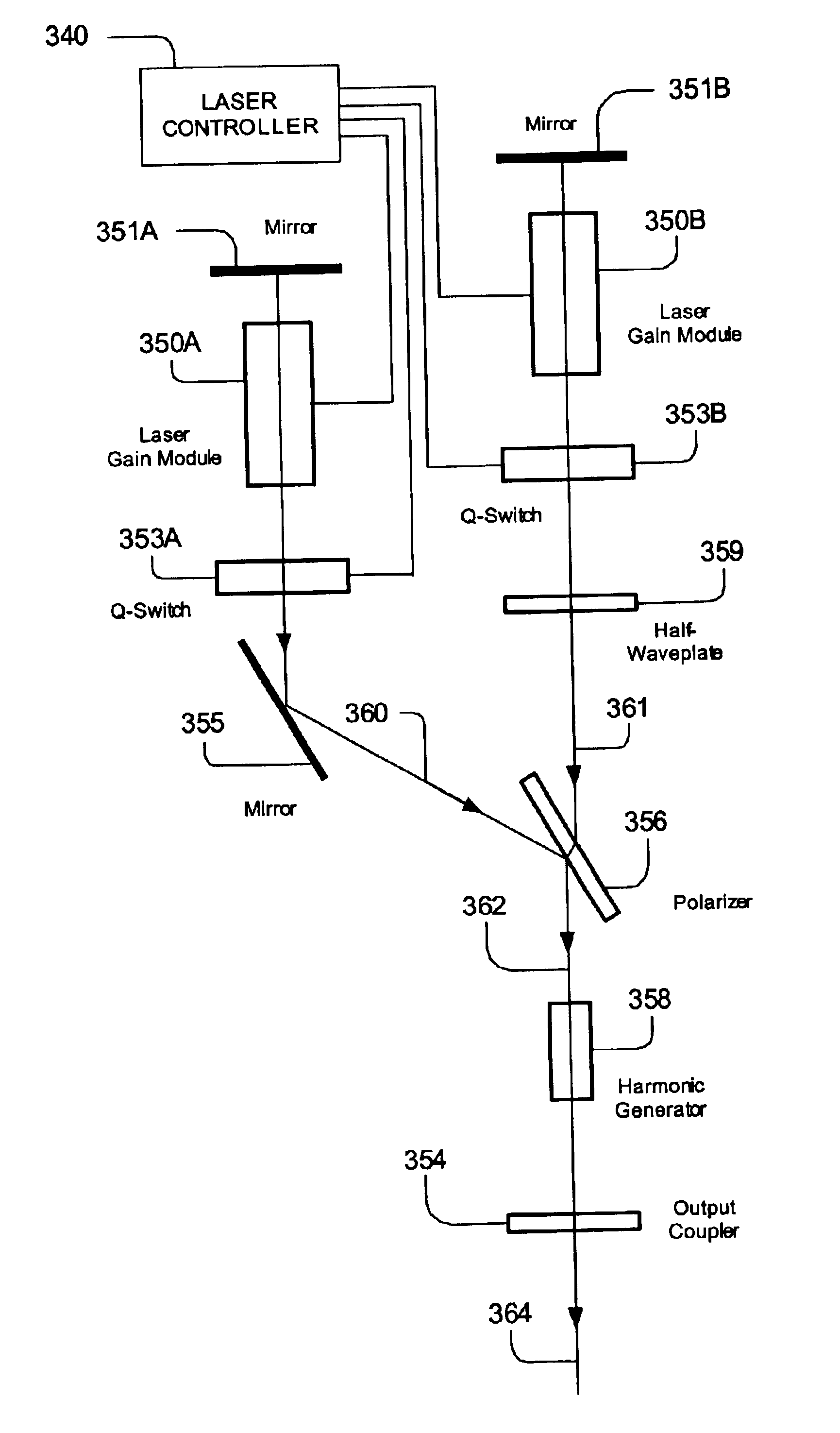
[0036]A detailed description of embodiments of the present invention is provided with reference to FIGS. 3-5.

[0037]A laser system diagram according to the present invention is provided in FIG. 3. The laser system of FIG. 3, includes a branched resonator, having two gain media (350A and 350B) and a single output coupler 354. The branched resonator has an output leg 362, a first gain leg 360 and a second gain leg 361. A first set of optical components defines the output leg 362 within the resonator, including the output coupler 354, a harmonic generator 358 and a polarizer 356. A second set of optical components including first mirror 351A, a first laser gain module 350A, a first Q-switch 353A, and mirror 355, define the first gain leg 360. The first gain leg defines an optical path through the first laser gain module 350A, between the polarizer 356 and the first mirror 351A. The laser system includes a third set of optical components, including a first mirror 351A, a second laser gai...


PUM


Abstract

A laser system includes a resonator having two gain modules generating pulses, coupled with intra-cavity polarization into a single beam line, using a single output coupler. A laser controller controls the laser heads to emit pulses in rapid succession, such as pulse pairs separated by a time interval of less than about 1 millisecond, and in some embodiments in a range from about zero (overlapping) to about 100 microseconds. Also a system adapted for metrology using particle image velocimetry PIV uses the resonator. For PIV, optics are provided in the output beam paths which expand the beam to form pulsed illumination sheets. A camera is used to capture images of the pulsed illumination sheets for analysis.

Description

BACKGROUND OF THE INVENTION[0001]1. Field of the Invention[0002]The present invention relates to systems and techniques for producing laser pulses in rapid succession, and to such laser systems used in the field of Particle Image Velocimetry (PIV).[0003]2. Description of Related Art[0004]In PIV, laser pulses are directed in rapid succession into a fluid flow, which in some cases includes tracer particles. A camera is used to capture images of the fluid flow during the pulses. The images captured can be analysed to determine characteristics of the flow. Often, a single exposure by the camera is used to capture the image during two pulses. For some embodiments, the laser pulses must be generated in rapid succession. Also, the laser pulses should be substantially equal in power and duration to simplify the analysis of the captured image or images. Finally, it is important for the laser pulses to illuminate the same space in the field of the camera during the successive pulses, because ...

Claims


Application Information

Patent Timeline
IPC IPC(8): H01S3/081H01S3/082H01S3/06H01S3/07
CPCH01S3/081H01S3/07H01S3/08054H01S3/0813H01S3/0815H01S3/082H01S3/109H01S3/11H01S3/1123
Inventor LIU, KUO-CHING
Owner ELEMENTAL SCI LASERS LLC
Why Eureka
Try Eureka