

Angular velocity sensor
a technology of angular velocity sensor and angular velocity, which is applied in the direction of acceleration measurement using interia force, turn-sensitive devices, instruments, etc., can solve the problems of complex structure as the entire sensor becomes complicated, and the inventor of this application cannot find any literature relating to multi-dimensional angular velocity sensor so far, and achieves the effect of simple structur
- Summary
- Abstract
- Description
- Claims
- Application Information
AI Technical Summary
Benefits of technology
Problems solved by technology
Method used
Image

Examples
first embodiment
§1 First Embodiment
Structure of Sensor According to First Embodiment
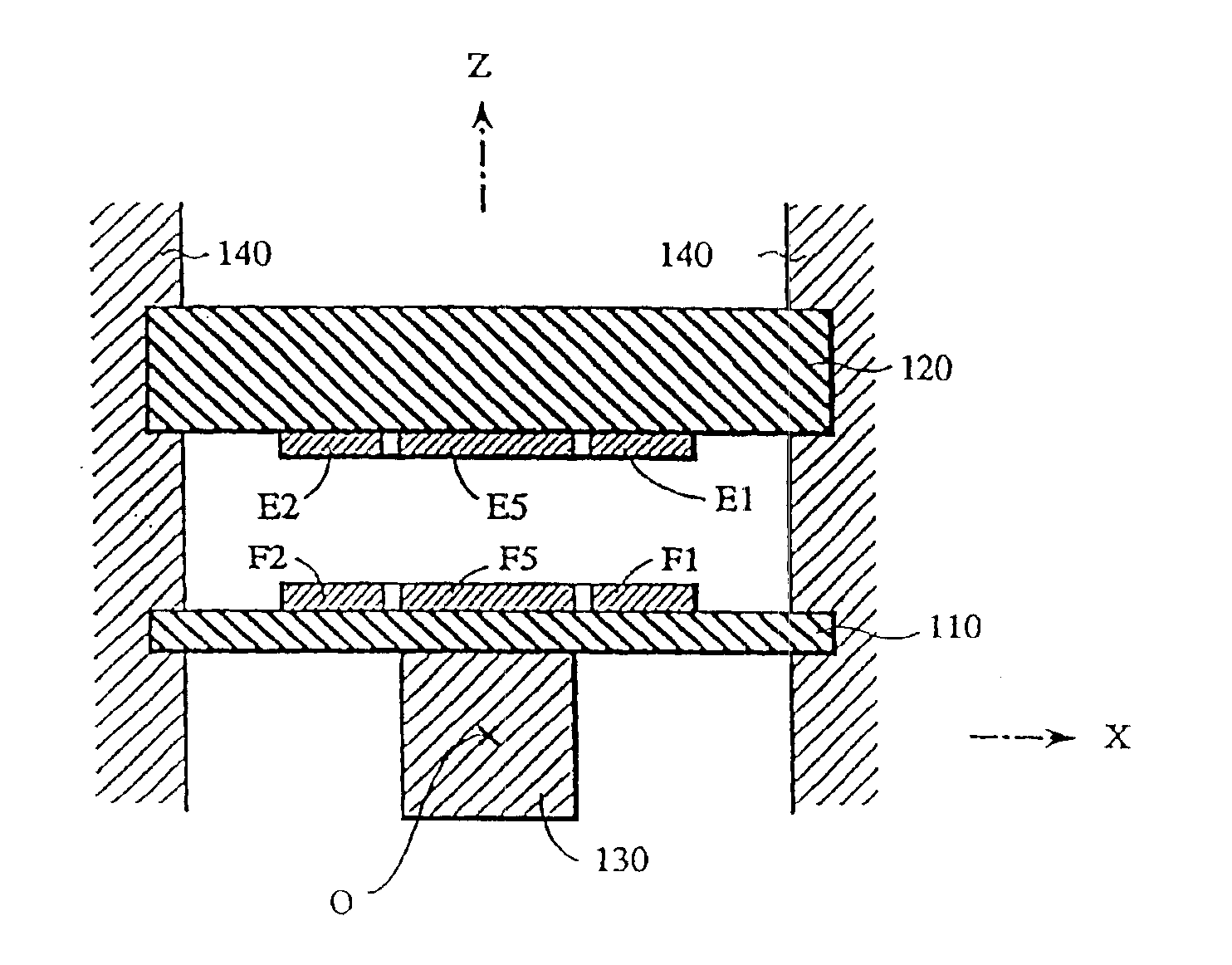
[0210]A multi-axial angular velocity sensor according to the first embodiment of this invention will be first described. The sensor of the first embodiment is a sensor in which a mechanism utilizing Coulomb force is used as the oscillation mechanism and a mechanism utilizing change of electrostatic capacitance is used as the detection mechanism.
[0211]FIG. 6 is a side cross sectional view of the multi-axial angular velocity sensor according to the first embodiment. A flexible substrate 110 and a fixed substrate 120 are both a disk-shaped substrate, and are disposed in parallel to each other with a predetermined spacing (distance) therebetween. On the lower surface of the flexible substrate 110, a columnar oscillator 130 is fixed. Further, the outer circumferential portion of the flexible substrate 110 and the outer circumferential portion of the fixed substrate 120 are both supported by a sensor casing 140. On the l...
second embodiment
§2 Second Embodiment
Structure of Sensor According to Second Embodiment
[0244]Subsequently, a multi-axial angular velocity sensor according to a second embodiment of this invention will be described. This second embodiment is also the same as the above-described sensor of the first embodiment in that a mechanism utilizing Coulomb's force is used as the oscillating mechanism and a mechanism utilizing change of electrostatic capacitance is used as the detecting mechanism. It should be noted that its structure is comprised of a plurality of substrates stacked, and is therefore more suitable for mass production.
[0245]FIG. 28 is a side cross sectional view of the multi-axial angular velocity sensor according to the second embodiment. This sensor includes, as its main components, a first substrate 210, a second substrate 220, and a third substrate 230. In this embodiment, the first substrate 210 is comprised of a silicon substrate, and the second and third substrates 220 and 230 are compri...
third embodiment
§3 Third Embodiment
Structure of Sensor According to Third Embodiment
[0261]Subsequently, a multi-axial angular velocity sensor according to the third embodiment of this invention will be described. While the third embodiment is the same as the previously described sensors of the first and second embodiments in that mechanism utilizing Coulomb's force is used as an oscillating mechanism, it is characterized in that mechanism utilizing a piezo resistance element is used as a detecting mechanism.
[0262]FIG. 35 is a side cross sectional view of the multi-axial angular velocity sensor according to the third embodiment. This sensor includes, as major components, a first substrate 310, a second substrate 320, a third substrate 330, and a fourth substrate 340. In this embodiment, the first and third substrates 310 and 330 are constituted with silicon substrate, and the second and fourth substrates 320 and 340 are constituted with a glass substrate. Such structure comprised of four layers of ...
PUM
 Abstract
Description
Claims
Application Information