Injection molded resin gear, injection molded resin rotating body, and injection molded article

a technology of injection molding resin and gear, which is applied in the direction of synthetic resin layered products, metal-working apparatuses, vehicle components, etc., can solve the problems of poor influence on the strength of the gear, color deviation, and bad influence on the precision of the tooth profil

Inactive Publication Date: 2005-09-13
ENPLAS CORP
View PDF9 Cites 12 Cited by
  • Summary
  • Abstract
  • Description
  • Claims
  • Application Information

AI Technical Summary

Benefits of technology

[0013]It is therefore an object of the present invention to eliminate the aforementioned problems and to provide a precision and inexpensive injection molded resin gear as compared with conventional injection molded resin gears.
[0014]It is another object of the present invention to provide a precision and inexpensive injection molded resin rotating body, such as an injection molded resin roller or an injection molded resin pulley, which is used for a power transmission mechanism similar to an injection molded resin gear.
[0015]It is a further object of the present invention to provide a precision and inexpensive injection molded article, such as a shaft supporting member, which substantially has the same shape of an injection molded resin roller and which can support thereon a movable shaft or a static shaft.
[0017]In this injection molded resin gear, a fillet portion for allowing the resin to smoothly flow from the hub to the web may be formed on a connecting portion of the rib to the hub. The rib has a radial length which is preferably 6W or less, more preferably 3W or less, assuming that a width of the rib W.

Problems solved by technology

That is, if the precision of the gears is bad, the rotation of the motor is not precisely transmitted to the image forming unit, so that operation failure, such as irregular rotation, is caused in the image forming unit, thereby causing print failure, such as color deviation.
If the weld lines 36 are produced in an injection molded article (the injection molded resin gear 31), there are some cases where the weld lines 36 do not only have a bad influence on the precision of the tooth profile, but they also have a bad influence on the strength of the gear.
Therefore, the injection molded resin gear 31 shown in FIG. 17 is unsuited for a power transmission device for a color copying machine or the like.
In addition, in the injection molded resin gear 41 formed by using the ring-shaped gate 42 as shown in FIG. 18, the amount of useless material used in the gate and runner is larger than that in the above described injection molded resin gear 31 using the pin point gates 35, so that there is a problem in that production costs are high.
As a result, an axial die 56 for forming an axial hole 55 can not securely be supported on the side of a top die 57, and the axial die 56 is easily moved by the injection pressure, so that there is a problem in that the axial hole 55 of the injection molded resin gear 51 is easy to be eccentric to have a bad influence on the results of measurement of run out of a tip circle.

Method used


Image

  • Injection molded resin gear, injection molded resin rotating body, and injection molded article
  • Injection molded resin gear, injection molded resin rotating body, and injection molded article
  • Injection molded resin gear, injection molded resin rotating body, and injection molded article

Examples


Embodiment Construction

[0049]Referring now to the accompanying drawings, particularly to FIGS. 1 to 16, the preferred embodiments of the present invention will be described below in detail.

[First Preferred Embodiment]

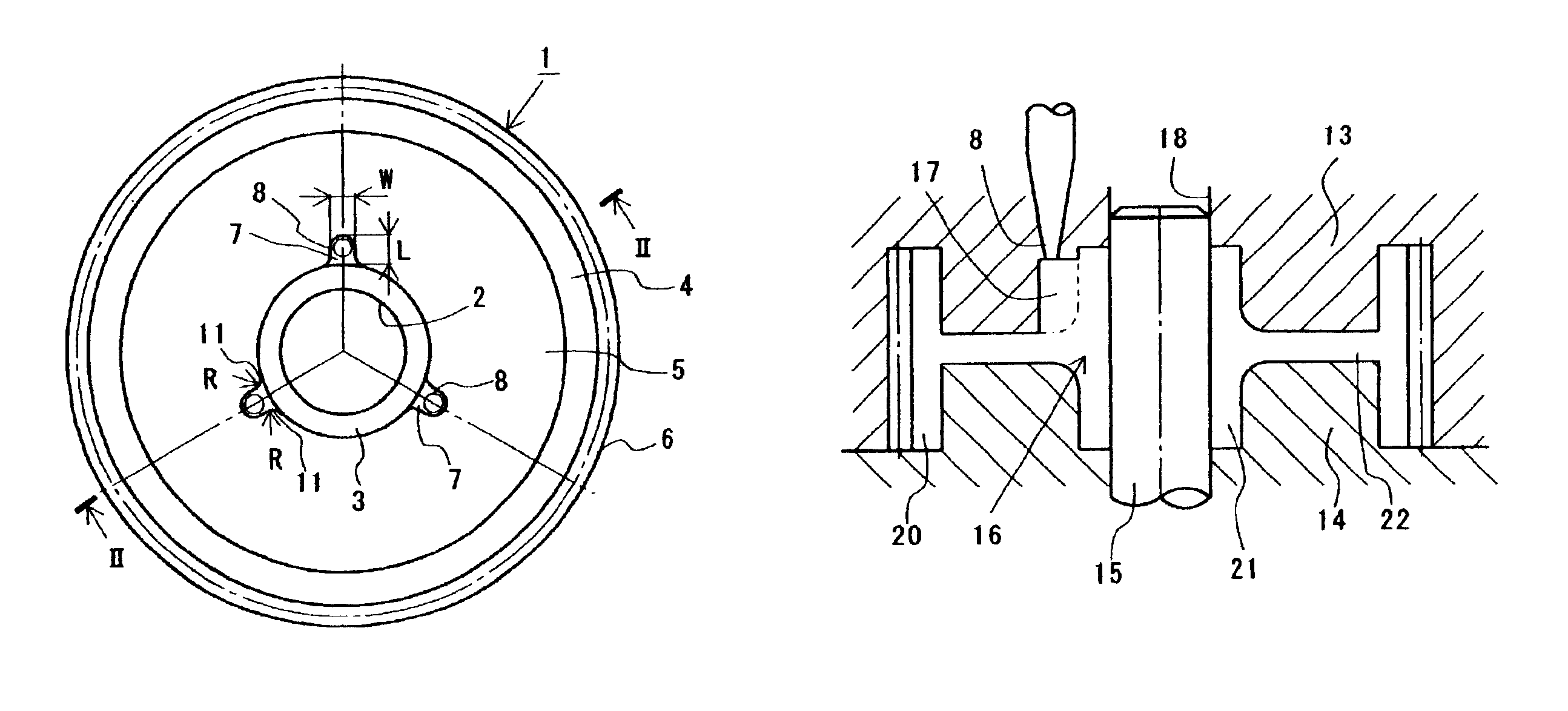
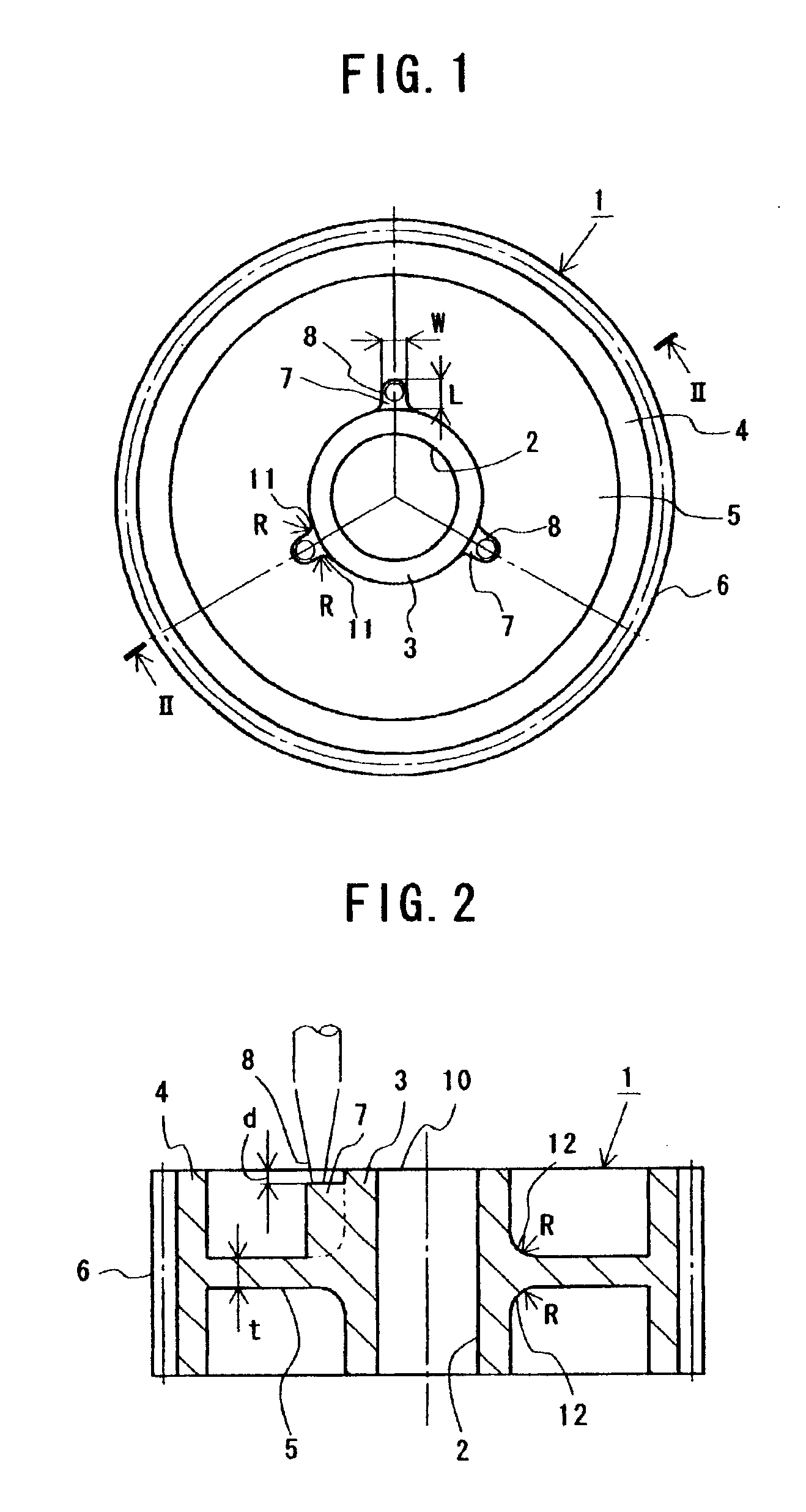
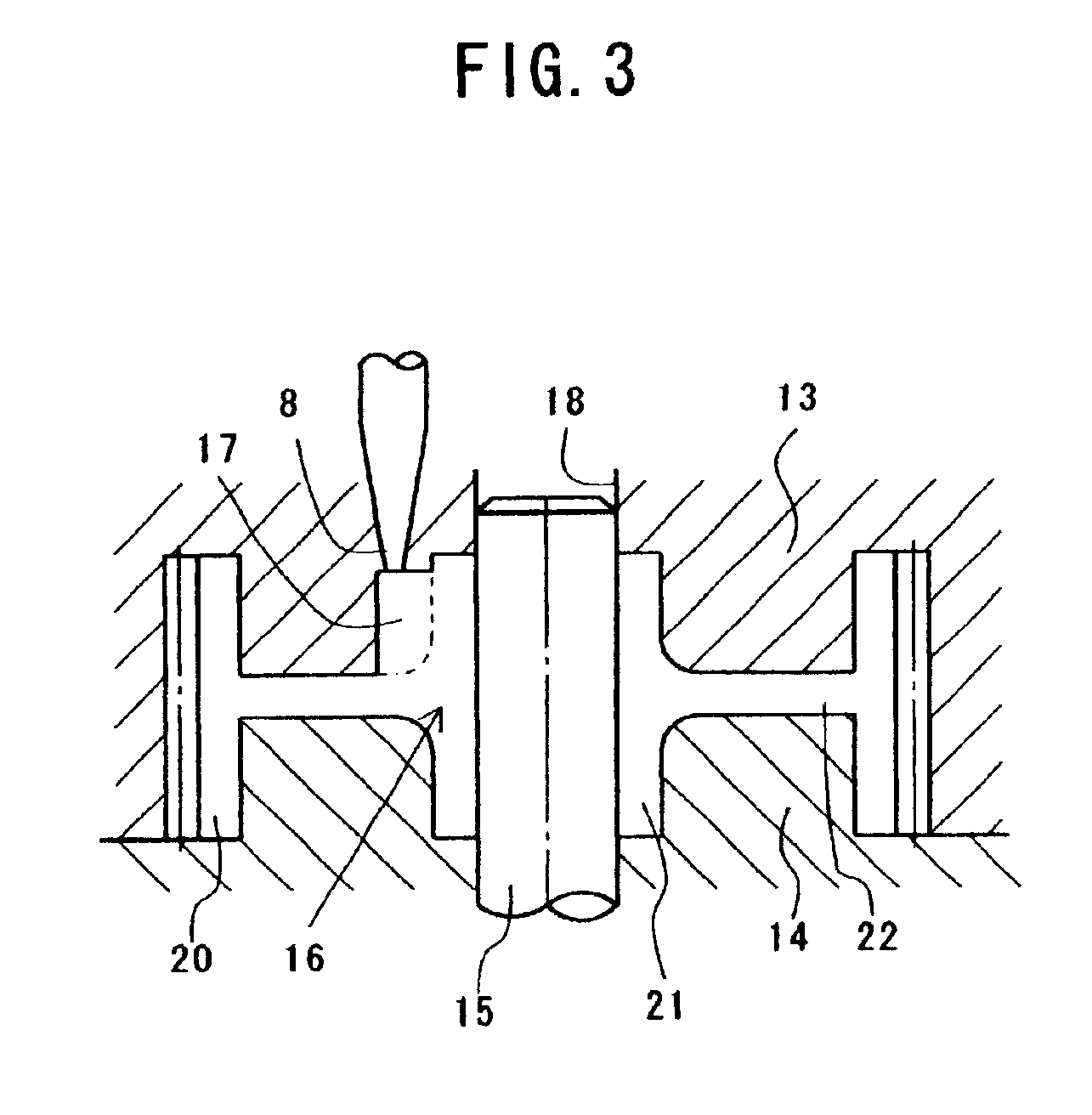
[0050]FIGS. 1 and 2 show the first preferred embodiment of an injection molded resin gear 1 according to the present invention, FIG. 1 being a side view of the injection molded resin gear 1 and FIG. 2 being a sectional view taken along line II—II of FIG. 1.

[0051]The injection molded resin gear 1 shown in these figures is formed by injecting a molten resin material, such as polyacetal, polyamide, polyphenylene sulfide or polybutylene terephthalate, into a cavity of a die from pin point gates.

[0052]The injection molded resin gear 1 comprises a substantially cylindrical hub (inner cylindrical portion) 3 having an axial hole 2, a substantially cylindrical rim (outer cylindrical portion) 4 arranged concentrically with the hub 3, and a web (disk-shaped portion) 5 connecting the hub 3 to the rim 4 i...


PUM

PropertyMeasurementUnit
radial lengthaaaaaaaaaa
widthaaaaaaaaaa
heightaaaaaaaaaa

Abstract

An injection molded resin gear 1 includes a rim 4, a hub 3 and a web 5 which connects the rim 4 to the hub 3. A plurality of ribs 7 for guiding a molten resin, which is injected from pin point gates 8, to the hub 3 protrude from the outer periphery of the hub 3 on one side of the web 5 so as to correspond to the pin point gates 8. The ribs 7 are formed so as to be recessed from the side face 10 of the hub 3. In the connecting portions of the ribs 7 to the hub 3, fillet portions 12 are formed for smoothly guiding the flow of the resin from the hub 3 toward the web 5 when the injection molded resin gear 1 is formed.

Description

BACKGROUND OF THE INVENTION[0001]1. Field of the Invention[0002]The present invention generally relates to a gear of a resin for use in power transmission devices for precision instruments, such as color copying machines, color printers and video tape recorders, various automotive parts, industrial equipments and so forth. More specifically, the invention relates to a resin gear which is formed by an injection molding. The present invention also relates to an injection molded resin gear and an injection molded resin rotating body, such as an injection molded resin roller or an injection molded resin pulley. Moreover, the present invention relates to an injection molded article which is used as a dynamic rotating body, such as an injection molded resin gear or an injection molded resin roller, or a static shaft supporting member.[0003]2. Description of the Prior Art[0004]For example, tandem type color copying machines and color printers are designed to sequentially carry out steps of...

Claims


Application Information

Patent Timeline
Patent Type & Authority Patents(United States)
IPC IPC(8): F16H55/06B29C45/27B29C45/37B29L15/00
CPCB29C45/0046F16H55/06B29C45/2708B29L2015/003Y10T74/1987Y10S74/10Y10T74/19967Y10T29/49464Y10T428/1352F16H2055/065
Inventor NOGUCHI, KOJINOGUCHI, TADASHI
Owner ENPLAS CORP
Why Eureka
Try Eureka