
Single-piece endoprosthesis with high expansion ratios and atraumatic ends

a single-piece, endoluminal technology, applied in the field of endoluminal prosthesis, can solve the problems of relatively soft graft wear, relatively high cost and processing cost, and raw tubular shape material, so as to improve the endoluminal prosthesis and reduce the amount of wear

Inactive Publication Date: 2005-09-13
ENDOVASCULAR TECH
View PDF34 Cites 42 Cited by
  • Summary
  • Abstract
  • Description
  • Claims
  • Application Information

AI Technical Summary

Benefits of technology

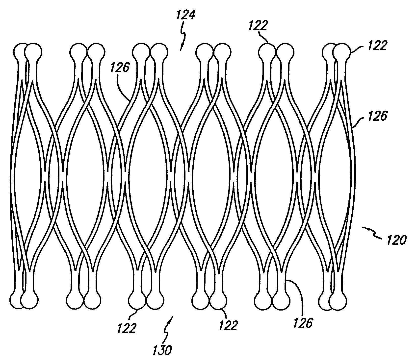
[0008]Briefly and in general terms, the present invention relates to an improved endoluminal prosthesis. This prosthesis may function as a stent or as a means to secure an endoluminal graft in a corporeal lumen such as an artery. The stent may include flattened bulbous tails to reduce the amount of wear between the stent and the softer graft material or corporeal lumen tissue. Stents typically are used to ensure the patency of diseased corporeal lumens by resisting collapse and occlusion. Endoluminal grafts typically are used to isolate diseased corporeal lumens from the flow of bodily fluids. The present invention also relates to a method of producing a tubular stent from a flat sheet of material.
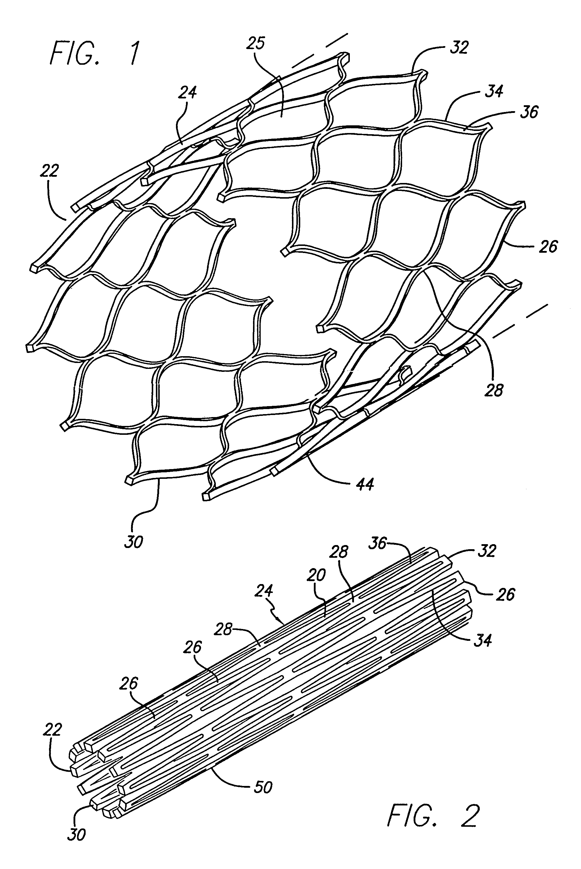
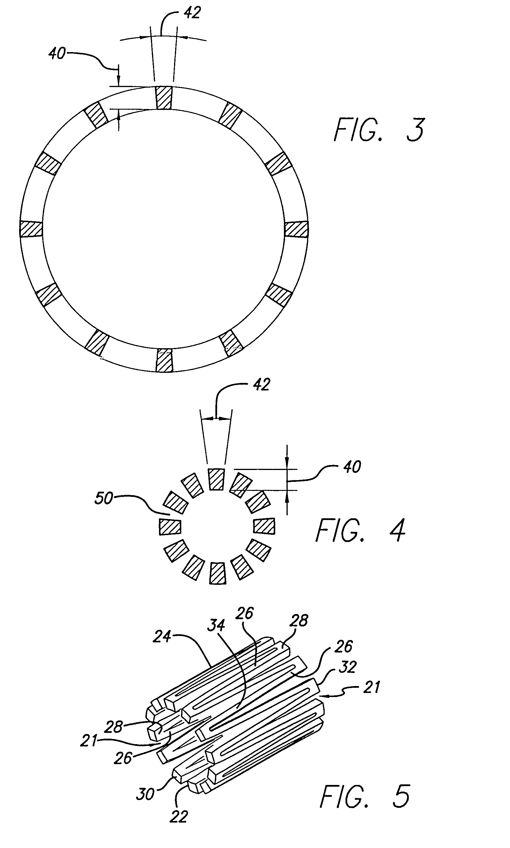
[0009]The prosthesis incorporating the present invention is configured as a series of intermittently merging curved beams (e.g. leaf springs) formed into a cylinder. This cylindrical structure is capable of being compressed into a small diameter and expanded into a large diameter. To facilitate both compression and expansion the beams have a cross-section which is greater in the radial direction (thickness) than in the circumferential direction (width). The beams of the present invention are also generally continuously curved to reduce or minimize stress concentrations in the structure. The beams straighten during compression until they are nearly straight.
[0010]While compressed the thickness of the beams prevents overlap. In a tightly packed configuration, the curved beams straighten out, come together and generally lie flat in close proximity to each other. The beams resist overlap because the thickness of each beam requires substantial radial displacement to move over or under the adjacent beam. The compression of the prosthesis may be maximized by configuring the beams to fit together tightly in a collapsed condition.

Problems solved by technology

Prior art stents for sealing a graft to corporeal lumen include narrow, sharp tails that can cause wear to the relatively soft graft.
Raw tubular shape material, as well as processing tubular shape material, is relatively more expensive than the cost and processing of the material in other forms.

Method used


Image

  • Single-piece endoprosthesis with high expansion ratios and atraumatic ends
  • Single-piece endoprosthesis with high expansion ratios and atraumatic ends
  • Single-piece endoprosthesis with high expansion ratios and atraumatic ends

Examples


Embodiment Construction

[0057]The following description, as well as the Figures, describe embodiments of the invention. These embodiments are exemplary of the inventors known uses of the invention, and are not intended to limit the scope of the claimed invention. Those skilled in the art of endoluminal devices will appreciate that the invention described herein may encompass many embodiments.

[0058]As shown in the Figures, the present invention relates to an endoluminal prosthesis. More particularly, the invention is an expandable and compressible prosthesis for repairing corporeal lumens. The prosthesis may be formed from a metallic cylinder by removal of cells. The invention also discloses a prosthesis with a flattened bulbous tail. The invention further discloses a stent being formed from a flat sheet of material.

[0059]As depicted in FIGS. 1 and 2, the result of removing cells 20 from the metallic cylinder 22 is a prosthesis 24 having a series of curved beams 26 and merge sections 28. It is to be recogni...


PUM


Abstract

A new endoluminal prosthesis for use in sealing a vascular graft to corporeal lumen provides for a flattened bulbous tail at the end of each cell of the prosthesis. The flattened bulbous tails reduce the amount of wear between the prosthesis and the softer material of the vascular grafts or corporeal lumen walls. A method of manufacturing a stent from a flat sheet of material is also included.

Description

RELATED APPLICATIONS[0001]This Application is a continuation-in-part of application Ser. No. 09 / 837,353 filed Apr. 17, 2001 entitled “Single Piece Endoprosthesis with High Expansion Ratios,” which is a continuation-in-part of application Ser. No. 09 / 546,966 filed Apr. 11, 2000 entitled “Single Piece Thick-Walled Endoprosthesis.”BACKGROUND OF THE INVENTION[0002]This invention relates to medical devices for the treatment of vascular diseases generally referred to as endoluminal prostheses. A variety of such devices are available for a broad range of treatment modalities. Examples of such devices are “vascular grafts” and “stents.” Vascular grafts are typically used to treat weakened areas of vessels known as aneurysms. Stents are typically used to prop open a narrowed or stenosed vessel.[0003]Stents and grafts may be delivered intraluminally through a narrow incision or a puncture in the patient's skin. The device may be mounted on a delivery catheter and inserted into a corporeal lum...

Claims


Application Information

Patent Timeline
Patent Type & Authority Patents(United States)
IPC IPC(8): A61F2/06A61F2/90
CPCA61F2/91A61F2/915A61F2002/075A61F2002/91508A61F2002/91516A61F2002/91533A61F2002/91541A61F2002/91558A61F2002/91575A61F2230/0013
Inventor POLLOCK, DAVID T.NEWHAUSER, RICHARDIANCEA, OCTAVIAN
Owner ENDOVASCULAR TECH
Learn More