Method of manufacturing wireless suspension blank

a technology of suspension blank and manufacturing method, which is applied in the direction of etching metal masks, instruments, integrated arm assemblies, etc., can solve the problems of high price of three-layer laminates, flying leads, and difficult working of metallic foils where finer working accuracy is required, and achieve high-quality methods.

Inactive Publication Date: 2005-09-13
DAI NIPPON PRINTING CO LTD
View PDF5 Cites 61 Cited by
  • Summary
  • Abstract
  • Description
  • Claims
  • Application Information

AI Technical Summary

Problems solved by technology

However, the above-mentioned process has a first problem in that the three-layered laminate used is high-priced.
Further, the above-mentioned process has a second problem in that working of metallic foil is difficult where finer working accuracy is required, since wet etching is made to the metallic foils laminated on both sides of polyimide resin film of three-layered laminates.
Further, the above-mentioned process has another problem in that flying leads used in checking the action of a magnetic head cannot be formed in a state wherein both sides thereof are exposed to the air.
However, dry etching has the following basic problem.
Namely, there is a problem that as shown in FIG. 2, a center of the laminate S goes up, in such an extent that the laminate S does not come into contact with cathode electrode 23, and therefore high throughput working becomes impossible.

Method used


Image

  • Method of manufacturing wireless suspension blank
  • Method of manufacturing wireless suspension blank
  • Method of manufacturing wireless suspension blank

Examples


Embodiment Construction

[0028]In order to explain in detail the present invention, referring to the drawings appended, the present invention is illustrated concretely.

The Method (1) of the Present Invention

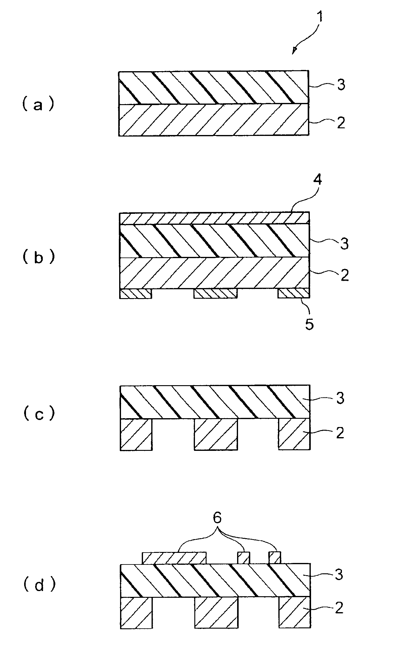
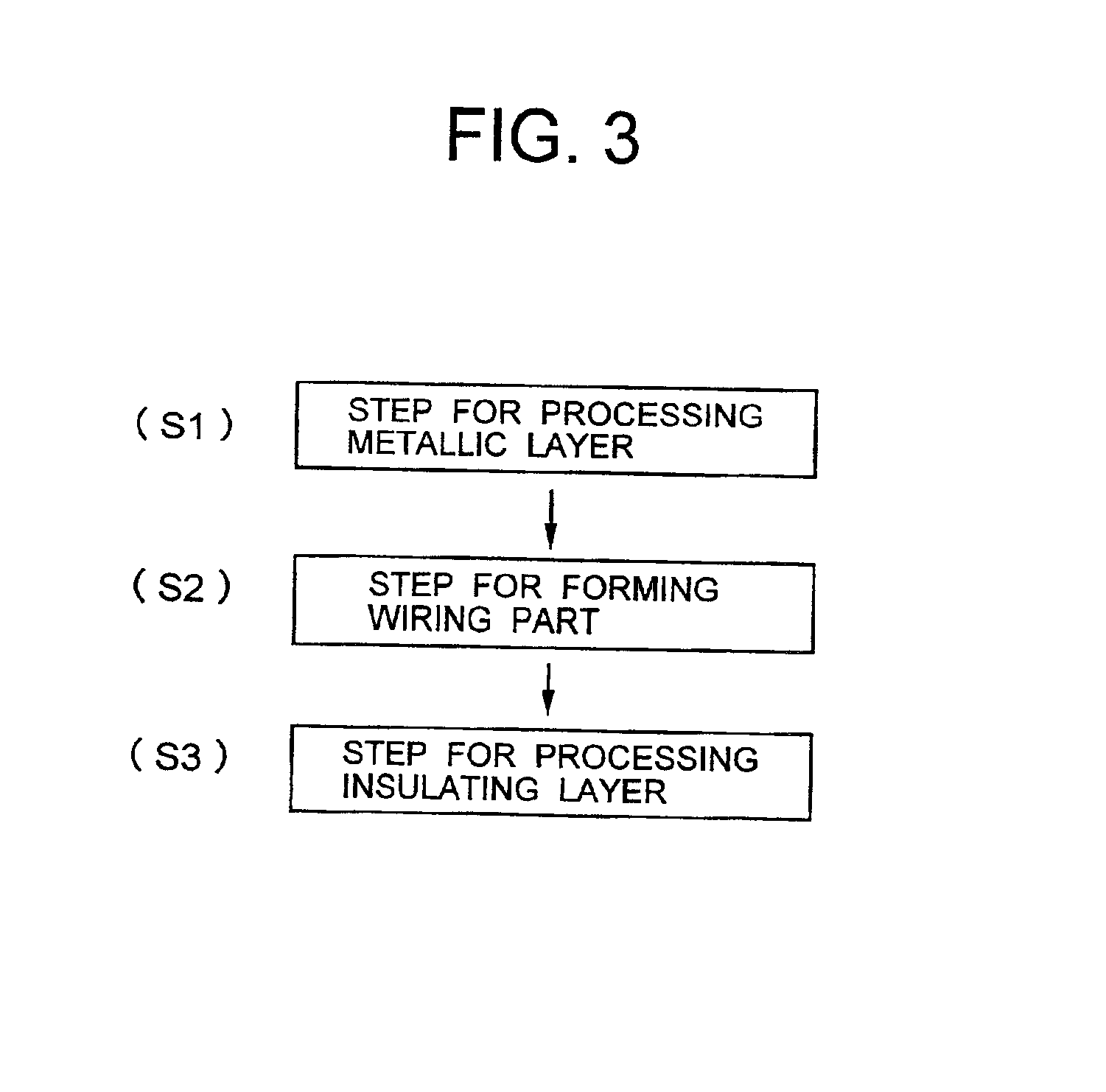
[0029]In the first method of the present invention, a wireless suspension blank shown in FIG. 3 is made using a two-layer laminate composed of a metallic layer with a spring property or characteristic and an electrically insulating layer. Namely, first, the working step of metallic layer is carried out in Step 1 (S1), and then the forming step of a wiring part is carried out in Step 2 (S2). Finally the working step of the insulating layer is carried out in Step 3 (S3).

[0030]The step 1 is a first step for working the metallic layer such as a stainless steel positioned on one side of the two-layered laminate. The step 2 is carried out after the metallic layer is processed in such a manner. The step 2 is a second step in which a wiring part is formed on an insulating layer such as a polyimide resin layer la...


PUM

PropertyMeasurementUnit
thicknessaaaaaaaaaa
pressureaaaaaaaaaa
pressureaaaaaaaaaa

Abstract

A wireless suspension blank is made using a two-layer laminate composed of a metallic layer with the spring property and an electrically insulating layer. The first method includes a first step for working the metallic layer by the photo etching method, a second step for forming a wiring part on the insulating layer by the semi-additive method and a third step for working the insulating layer by the wet-etching method. The second method includes a first step for working the metallic layer by the photo etching method, a second step for forming a wiring part on the insulating layer by the semi-additive method and a third step for working the insulating layer by the plasma etching method. The third method includes a first step for forming a wiring part on the metallic layer by the semi-additive method, a second step for working the metallic layer by the wet-etching method and a third step for working the insulating layer by the dry-etching method or the wet-etching method. The use of a two-layer laminate makes possible a low cost production. Further, the forming of a wiring part by the semi-additive method makes possible to working very accurately a fine wiring part.

Description

[0001]The present invention relates to a method of manufacturing a wireless suspension blank used in a hard disc drive (hereafter called “HDD”) as a data storage device and the like.BACKGROUND OF THE INVENTION[0002]Prior art concerning such a method of manufacturing the above-mentioned member for electric parts is mentioned in Japanese Patent Laid-open 2000-49195 (Title of Invention: “Process for making a member for electric parts”), in which a method of manufacturing a wireless suspension blank used for HDD is not concretely explained on a method of manufacturing a wireless suspension blank. However, a method of manufacturing a member for electric parts is disclosed as follows.[0003]In the method, a three-layered laminate composed of a polyimide resin film and metallic foils laminated on both sides of the polyimide resin film is used as a laminate. In the process, resist patterns are formed on the metallic foils laminated on both sides of the polyimide, respectively, and the two me...

Claims


Application Information

Patent Timeline
Patent Type & Authority Patents(United States)
IPC IPC(8): G11B5/48H05K3/00H05K1/05H05K3/06H05K3/10
CPCG11B5/4833G11B5/484G11B5/486H05K3/0017H05K1/056H05K3/002H05K3/0041H05K3/064H05K3/108H05K2201/0394H05K2201/0969H05K2203/0554
Inventor YAGI, HIROSHIKAWANO, SHIGEKIUMEDA, KAZUOTAKEI, JIROIIMURA, YUKIOSASAKI, SATOSHISAKAYORI, KATSUYAAMASAKI, HIROKO
Owner DAI NIPPON PRINTING CO LTD
Why Eureka
Try Eureka