Reduced crossmodulation operation of a multimode communication device

a multi-mode communication and cross-modulation technology, applied in the direction of transmission, transmission, electrically long antennas, etc., can solve the problems of cross-modulation, intermodulation distortion, network system penalized in capacity loss,

Inactive Publication Date: 2005-09-13
GOOGLE TECH HLDG LLC
View PDF11 Cites 47 Cited by
  • Summary
  • Abstract
  • Description
  • Claims
  • Application Information

AI Technical Summary

Problems solved by technology

However, the network system is penalized in capacity lost by the compressed event.
However, it may still be a requirement for the device to use a compressed uplink mode.
Unfortunately, there are cases where the transmitter and receiver frequencies can crossmodulate causing intermodulation distortion.
In particular, crossmodulation arises when the communication device transmitter leakage modulates an interferer in a receiver.
Crossmodulation manifests itself in receiver stages with insufficient linearity such as mixers and amplifiers.
The non-linearities create higher-order frequency intermodulation products which may fall in-band in a receiver causing interference.
In particular, a receiver gain stage, can be a large source for intermodulation distortion due to its early placement in the receiver input path (i.e. the gain stage has the most exposure to transmitter leakage).
Crossmodulation problems are understood in duplex CDMA systems where it leads to high third-order intercept performance requirements and thus high current dissipation requirements.
Out-of-band signals, such as signals out of the licensed spectrum band, and in particular, signals out of the channelized band can be interferers.
This out-of-band signal power along with intermodulation products degrade receiver performance resulting in decreased signal-to-noise (or carrier-to-interference) ratio and degraded receiver sensitivity.
This results in the desired in-channel signal being degraded due to undesired signals being translated (frequency shifted) into the desired band.
Filtering is ineffective here since interference and intermodulation products may have been frequency translated to the desired channel, allowing them to pass through to the receiver backend.
Compressed mode can alleviate some of these problems, however, it is undesirable to use compressed mode since system capacity is reduced and potentially data throughput reduced in the event that the device is resource limited.
Although the prior art has addressed crossmodulation in duplex CDMA receivers, some systems, such as a stand alone GSM receiver, do not have the performance to meet crossmodulation and high third-order intercept point requirements.
However, this adds to the cost of the device and would also lead to excessive current dissipation.
However, interference cancellation techniques have not been viable to date due to implementation complexities.
Again, tunable RF circuits / filters are not a viable technology to date.
Also, a tunable filter may not help the crossmodulation problem, such as if a GSM reception is on one side of the receiver frequency band and a WCDMA reception / transmission is on the other side of the receiver frequency band.
However, channel quality can be degraded by other things besides intermodulation.
Therefore, the prior art would improperly supply corrections (requiring more current) even if intermodulation were not the cause of the present degraded signal condition.
Moreover, the above techniques are limited to all CDMA systems where a CDMA quality metric is used and thus these methods do not address the GSM case.
Furthermore, these techniques do not address the simultaneous reception scenario where the mobile device can switch to uplink compressed mode if needed to avoid the crossmodulation degradation in the non-duplex receiver.

Method used


Image

  • Reduced crossmodulation operation of a multimode communication device
  • Reduced crossmodulation operation of a multimode communication device
  • Reduced crossmodulation operation of a multimode communication device

Examples


Embodiment Construction

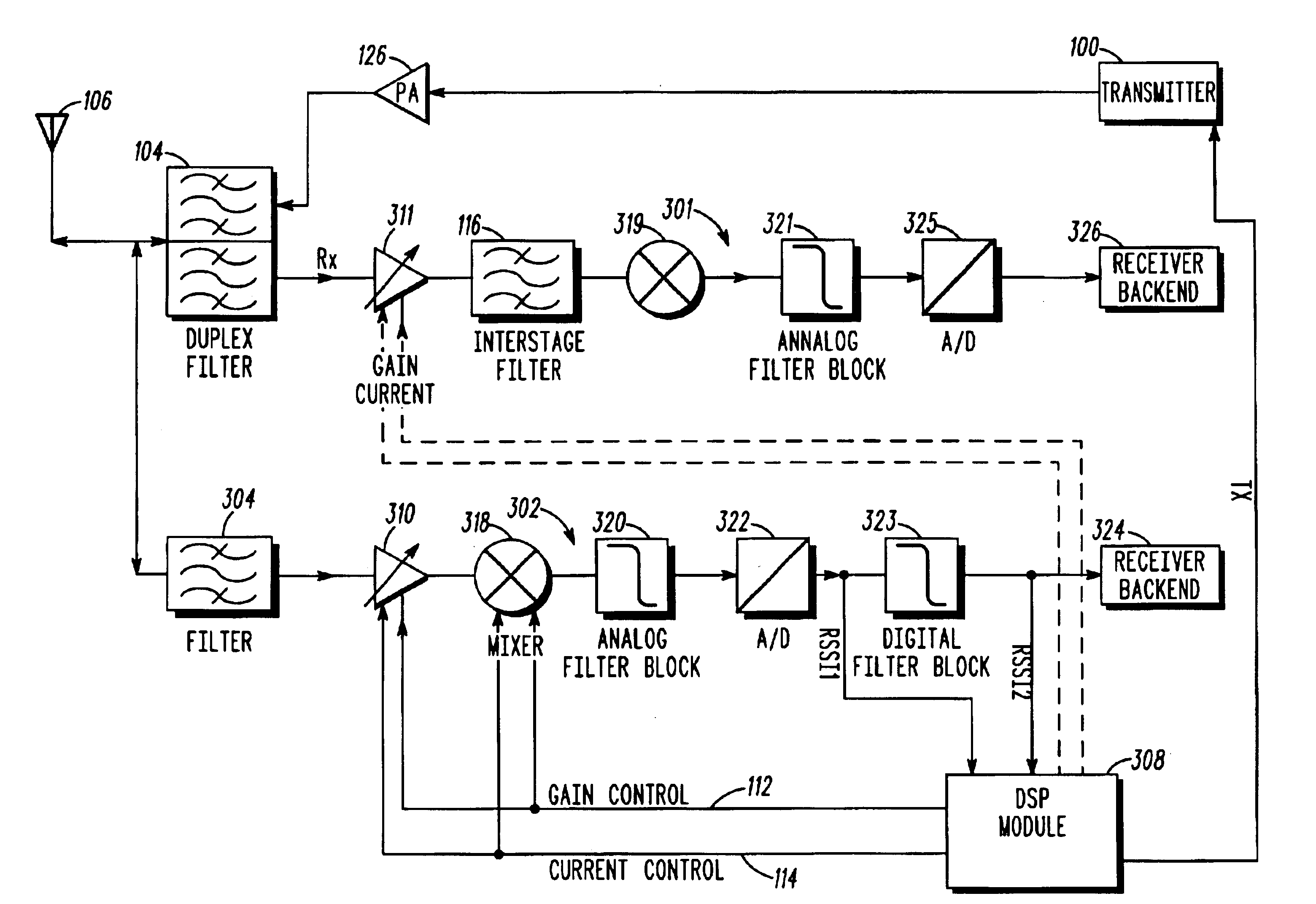
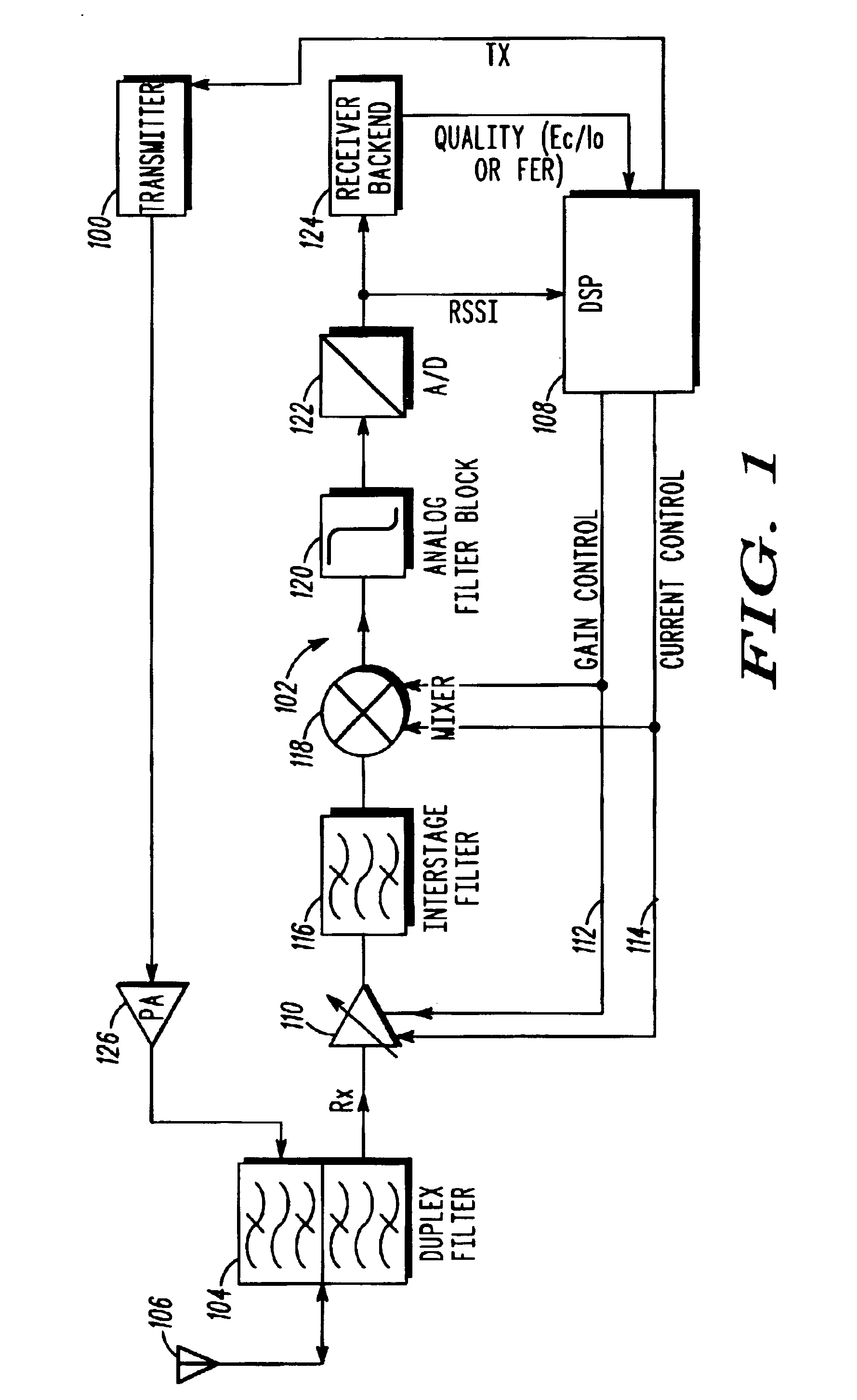
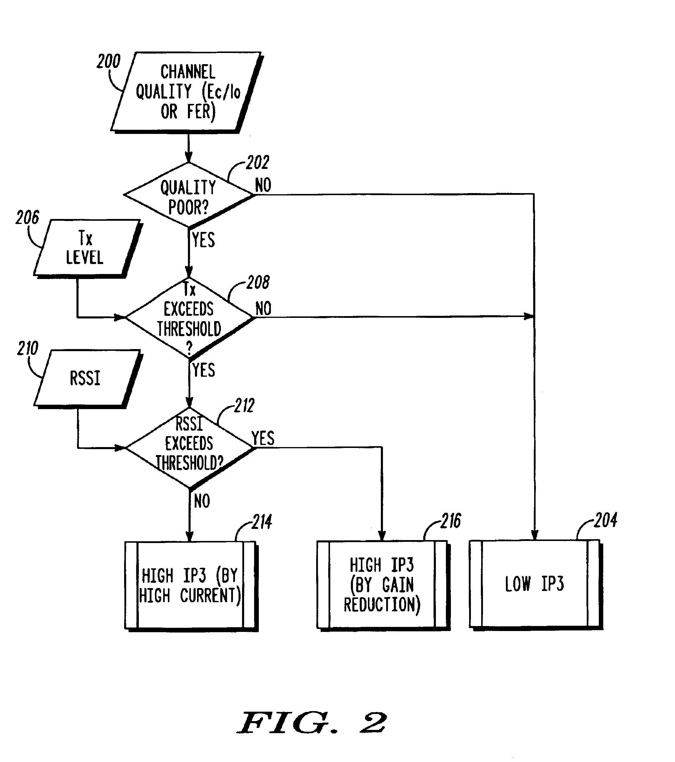
[0019]The present invention provides a unique method to improve reception in a multimode receiver circuit for a wireless communications device in a communication system. The invention also addresses compressed, uncompressed, and GSM modes of operation. In particular, the present invention reduces the effects of intermodulation distortion from crossmodulation by improving linearity of the receiver only when intermodulation is detected or anticipated, and while allowing operation in uncompressed mode, thereby improving data throughput. This improvement is accomplished without any significant additional hardware or cost in the communication device. Instead of incorporating high linearity circuitry, which in turn adds cost and increases current drain, the present invention advantageously utilizes the existing circuitry in combination with solutions for processing of the RF input signals necessary in a multimode communication device. This invention further allows selective operation in c...


PUM


Abstract

A method to reduce crossmodulation in a multimode radio communication device with a transmitter, a receiver, and a second receiver (400) that operates in a receiver channel bandwidth (402) includes a step of measuring a first signal strength in the receiver channel bandwidth (404), a second signal strength outside of the receiver channel bandwidth (406), and a power level of the transmitter. A next step (408) includes determining a signal-to-crossmodulation interference ratio (SCMIR). A next step (410) includes calculating a SCMIR threshold. A next step (412) includes comparing the ratio to the threshold. A next step (416,420) includes increasing the linearity of the receiver if the ratio is less than the threshold.

Description

FIELD OF THE INVENTION[0001]The present invention relates to the control of operating modes of a radio communication device. More particularly the invention relates to improving immunity to interferences during reception in a multimode radio communication device.BACKGROUND OF THE INVENTION[0002]New digital cellular communication systems, such as the Wideband Code Division Multiple Access (WCDMA) extension of the Global System for Mobile Communication (GSM) and Digital Cellular System (DCS) can utilize different operating modes for the transfer of digital information. For example, digital information can be transferred using two different duplex modes, Frequency Division Duplex (FDD) and Time Division Duplex (TDD), as are known in the art, and use different operating frequency bands. The GSM system operates in the 900, 1800 and 1900 MHz bands. In addition, a communication can share CDMA and Time Division Multiple Access (TDMA) aspects.[0003]Multimode communication devices are designe...

Claims


Application Information

Patent Timeline
Patent Type & Authority Patents(United States)
IPC IPC(8): H04B1/10
CPCH04B1/1027H04B1/109
Inventor HAUB, DAVIDKURBY, CHRISTOPHERMACH, RICHARDVANNATTA, LOUIS
Owner GOOGLE TECH HLDG LLC
Why Eureka
Try Eureka