Surface mounter for mounting components

a technology for mounting components and surface mounters, which is applied in the direction of manufacturing tools, instruments, transportation and packaging, etc., can solve the problems of occupying a large space and complicated structure of the surface mounter with dual lanes, and achieve the effect of improving the efficiency of mounting components and less spa

Inactive Publication Date: 2005-09-20
HANWHA TECHWIN CO LTD
View PDF7 Cites 25 Cited by
  • Summary
  • Abstract
  • Description
  • Claims
  • Application Information

AI Technical Summary

Benefits of technology

[0011]The present invention provides a surface mounter which occupies less space and offers improved component mounting efficiency, and also a method of mounting components using the same.

Problems solved by technology

However, the surface mounter with dual lanes has a complicated structure and occupies a larger space because its dual-lane PCB transferring areas and component mounting areas take the space.

Method used


Image

  • Surface mounter for mounting components
  • Surface mounter for mounting components
  • Surface mounter for mounting components

Examples


Embodiment Construction

[0022]Preferred embodiments of the present invention are herein described in detail with reference to the appended drawings.

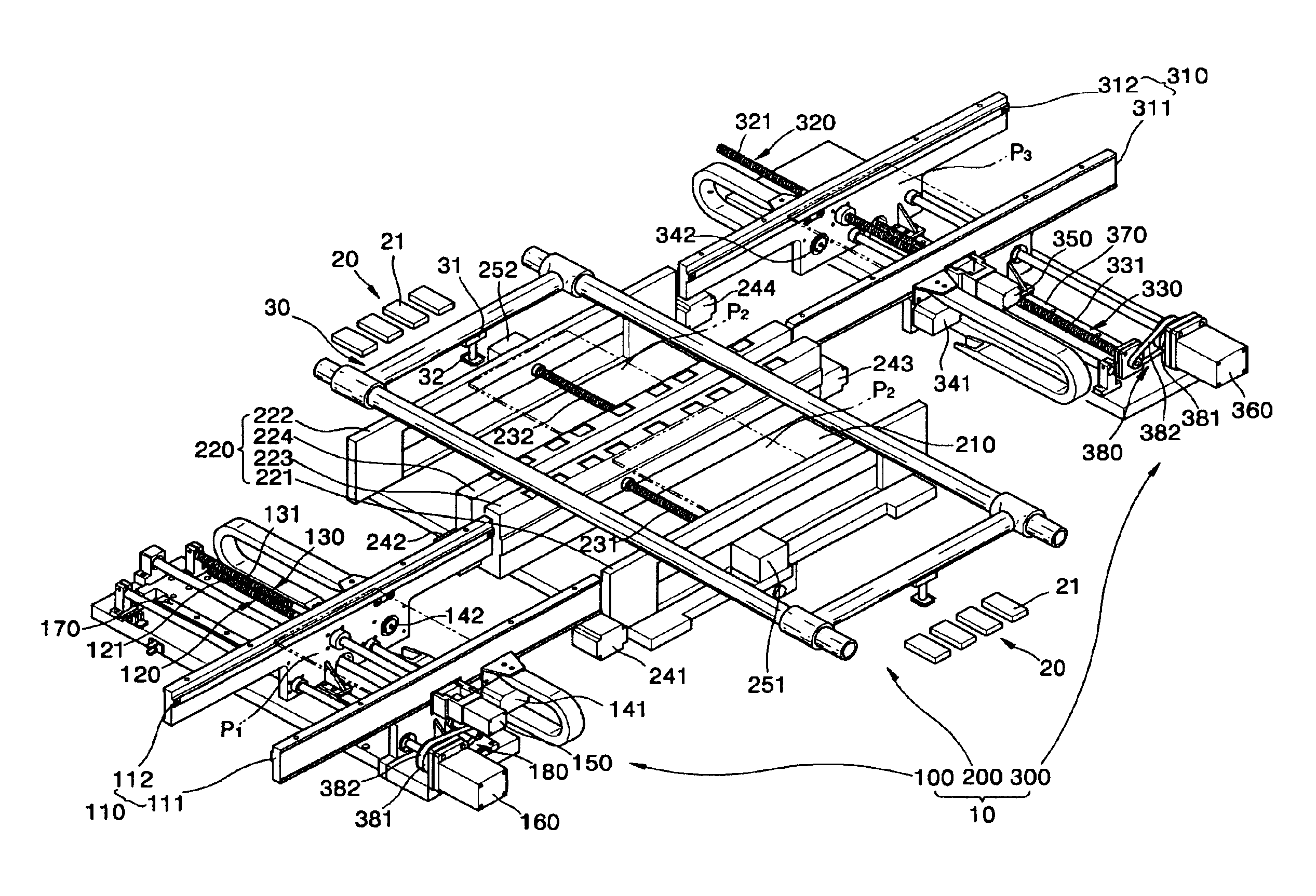
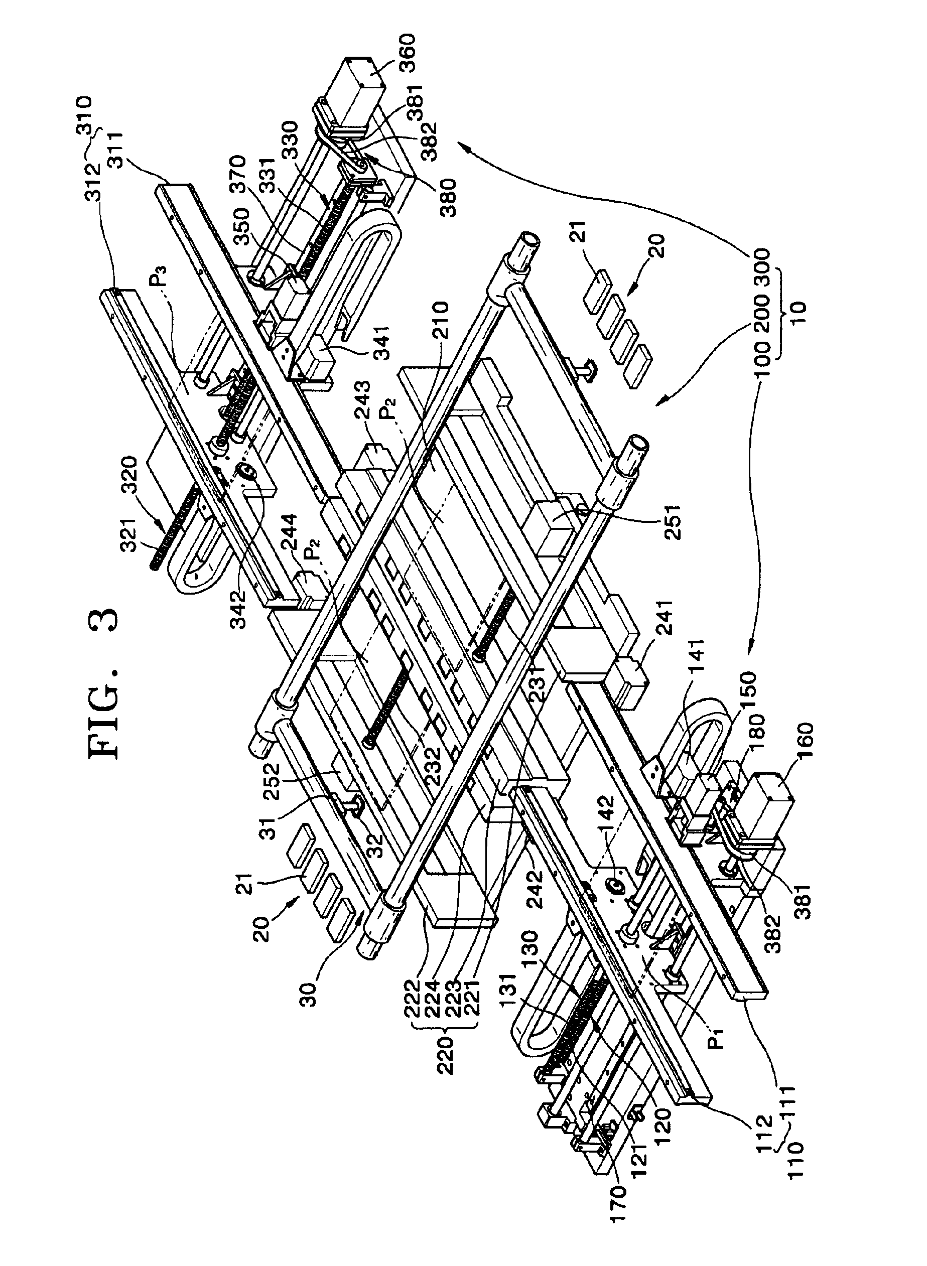
[0023]FIG. 3 is a perspective view of a surface mounter according to an embodiment of the present invention, and FIG. 4 is an enlarged view of a carry-in portion of a transfer unit in FIG. 3.

[0024]Referring to FIGS. 3 and 4, the surface mounter according to an embodiment of the present invention includes a transfer unit 10 which transfers electronic circuit boards (PCBs) P1, P2, and P3 to a mounting position, a component supply unit 20 which selectively supplies components using a plurality of component feeders 21, and a head unit 30 which has a mounting head 31 with a suction nozzle 32 for mounting a component (or a plurality of components) on PCB P2 by lifting or picking up the component with suction applied from the suction nozzle 32.

[0025]The transfer unit 10 includes a carry-in portion 100 with a single distribution lane 110 along which PCB P1 is transport...


PUM

PropertyMeasurementUnit
widthaaaaaaaaaa
widthsaaaaaaaaaa
structureaaaaaaaaaa

Abstract

A surface mounter includes: a component supply unit in which a plurality of components to be mounted are placed; a head unit which mounts a component on a circuit board by lifting the component from the component supply unit with suction; and a transfer unit including a carry-in portion with a single distribution lane, a mounting portion with dual working lanes, and a carry-out portion with a single carry-out lane, wherein a circuit board is transferred along the distribution lane and distributed to the mounting portion, components are mounted on the circuit board stopped at a position of the mounting portion, and the circuit board with the components mounted thereon is transferred out of the transfer unit along the carry-out lane. In the surface mounter, a number of circuit boards can be distributed to dual working lanes via a single distribution lane, not via common dual carry-in lanes, at higher working speed, so that working efficiency is improved. In addition, the surface mounter occupies less space.

Description

CROSS-REFERENCES TO RELATED APPLICATIONS[0001]This application claims priority from Korean Patent Application No. 2002-32847, filed on Jun. 12, 2002, in the Korean Intellectual Property Office, the disclosure of which is incorporated herein in its entirety by reference.BACKGROUND OF THE INVENTION[0002]1. Field of the Invention[0003]The present invention relates to an apparatus and method of mounting various kinds of electronic chips or device components on a printed circuit board (PCB), and more particularly, to an apparatus and method of mounting components with higher working and space-utilization efficiency.[0004]2. Description of the Related Art[0005]In general, chip mounters or surface mounters are used to mount semiconductors or other kinds of electronic chips and / or components (hereinafter referred to as “chip”, “chips”, “component”, or “components”) at predetermined positions on a printed circuit board (hereinafter referred to as “PCB” or PCBs”). For the mounting, a PCB is t...

Claims


Application Information

Patent Timeline
Patent Type & Authority Patents(United States)
IPC IPC(8): H05K13/08H05K13/00H05K13/04G02F1/13H05K13/02
CPCH05K13/046H05K13/08Y10T29/5196Y10T29/53265Y10T29/53178Y10T29/53261Y10T29/53174H05K13/0061G02F1/13
Inventor CHO, TAE-YEONLEE, SEONG-I
Owner HANWHA TECHWIN CO LTD
Why Eureka
Try Eureka