Check valve for use in filler tube vapor recirculation system and method of making same

Inactive Publication Date: 2005-09-20
EATON CORP
View PDF5 Cites 50 Cited by
  • Summary
  • Abstract
  • Description
  • Claims
  • Application Information

AI Technical Summary

Benefits of technology

[0004]The present invention provides a solution to the above-described problem of preventing liquid fuel, upon rising in the filler tube when the tank is full, from entering into the vapor recirculation line tapped into the filler tube below the nozzle seal. The present invention employs an insert which may be disposed in an existing filler tube without requiring a rework of the filler tube and includes a flexible membrane or flapper-type check valve attached to the insert for placement in the filler tube prior to attaching the mechanical seal portion of the filler tube. The insert also includes, preferably formed integrally therewith as a single piece, a deflectable ground strap / tab for insuring electrical grounding of the nozzle to the vehicle structure upon insertion of the nozzle into the filler tube and through the filler tube nozzle seal. The check valve of the present invention employs a flexible membrane which is operative to close the vapor recirculation port in the filler tube upon entry of liquid fuel in the upper end of the filler tube. The check valve membrane is nevertheless sufficiently flexible to open under slight vapor pressure in the recirculation tube and thus permits flow of vapor into the filler tube for proper vapor recirculation. A spring tab, preferably integrally formed with the insert, positions the membrane adjacent the recirculation port.

Problems solved by technology

In the aforesaid fuel tank filler tube installations having a vapor recirculation tube attached to a port in the filler tube below the nozzle seal, problems have been encountered where liquid fuel rising in the filler tube, upon the tank becoming filled, has resulted in liquid fuel entering the vapor recirculation tube and flowing into the vapor vent system.
Liquid fuel in the vapor vent system can result in blockage of the vapor vent lines by fuel trapped in low regions or in some cases liquid fuel entering into the vapor storage canister causing degradation of the vapor storage medium in the canister.

Method used


Image

  • Check valve for use in filler tube vapor recirculation system and method of making same
  • Check valve for use in filler tube vapor recirculation system and method of making same
  • Check valve for use in filler tube vapor recirculation system and method of making same

Examples


Embodiment Construction

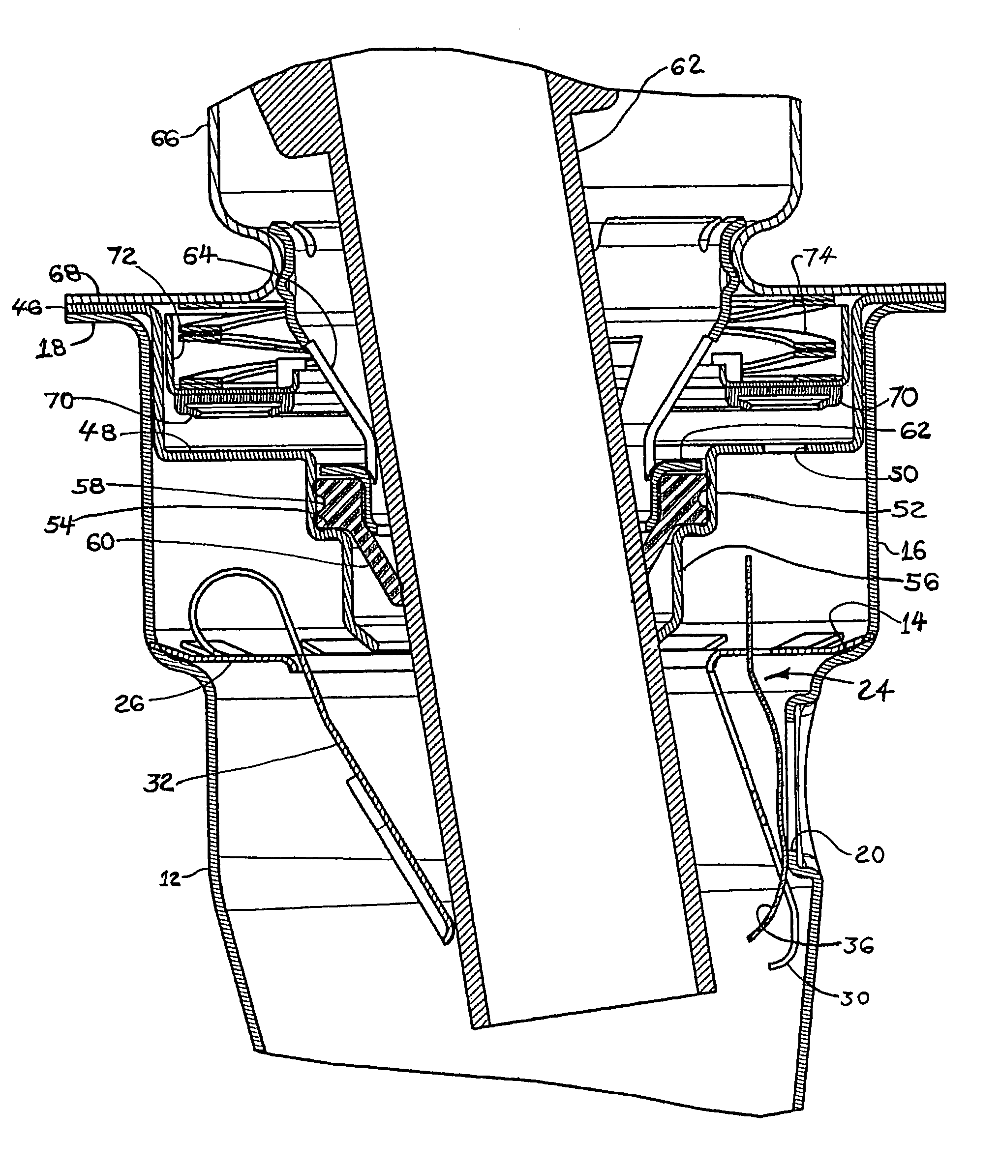
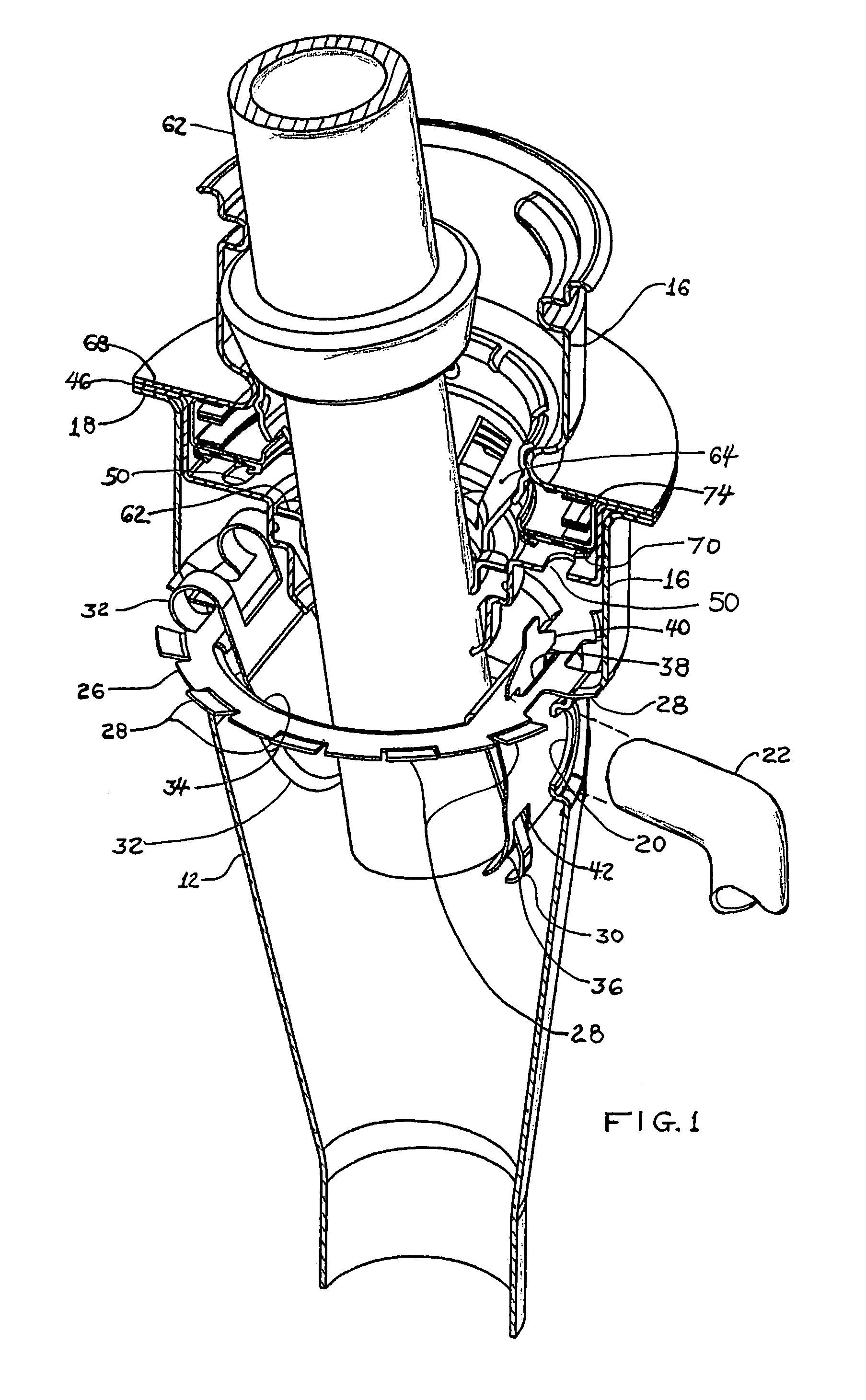
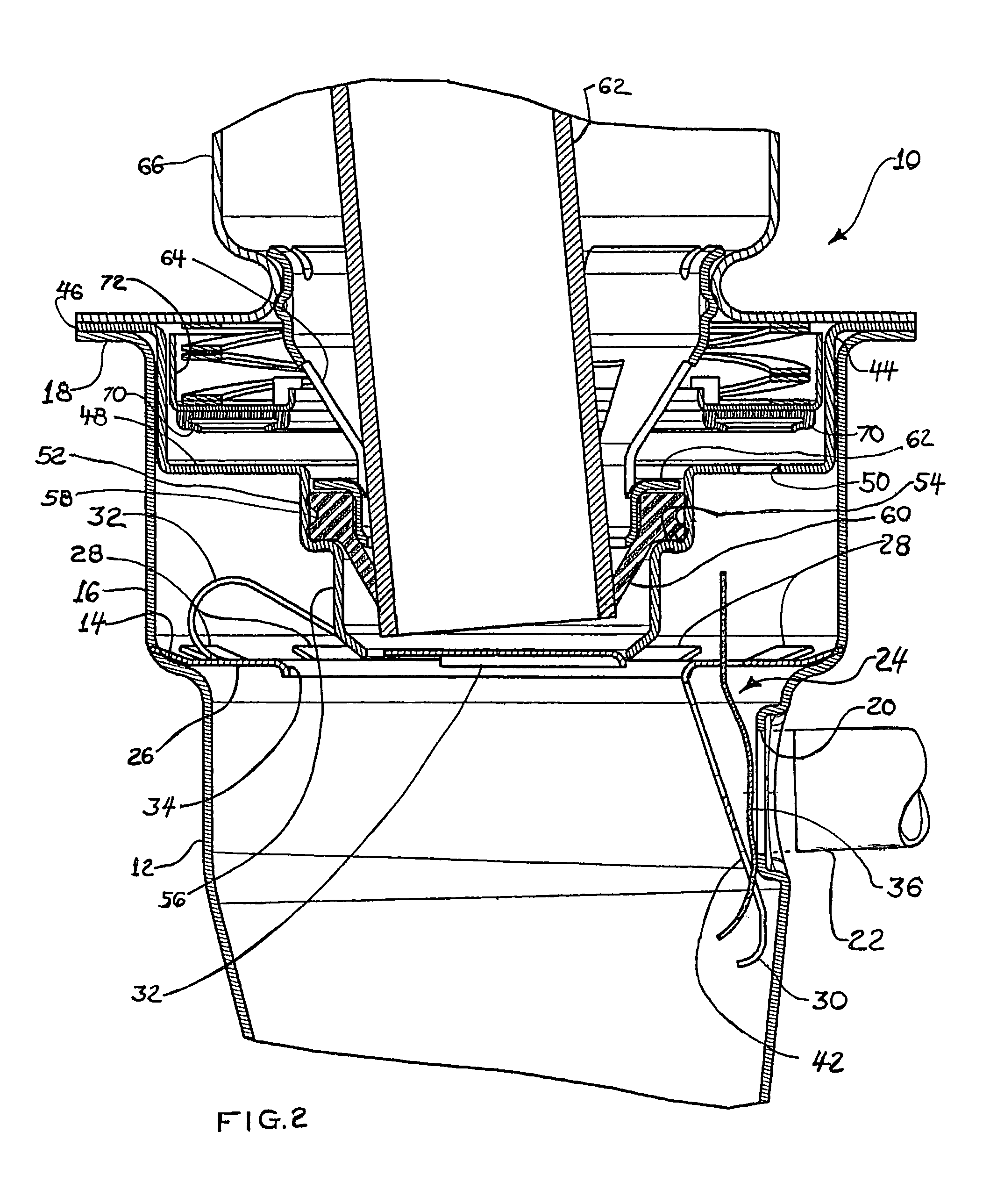
[0009]Referring to FIGS. 2 and 3, the present invention is shown embodied in a fuel tank filler tube as indicated generally at 10 with the upper end of the filler tube denoted by reference number 12. An annular step or shoulder 14 is formed on the tube 12 which transitions the tube to an enlarged diameter portion 16 having an outwardly extending flange 18 formed at the upper end thereof. The tube 12 has a recirculation port or aperture 20 formed therein which is adapted for having a recirculation tube 22 connected thereto as is well known in the art of fuel tank vapor systems.

[0010]A combination vapor check valve and ground strap assembly is indicated generally at 24 and includes an annular plate 26 having a plurality of friction tabs 28 formed about the circumference thereof. Upon installation of the assembly 24 in tube 16, tabs 28 frictionally engage the inner surface of the wall of the tube portion 16 to maintain the insert against the shoulder 14. The insert plate 26 has formed,...


PUM

PropertyMeasurementUnit
Flexibilityaaaaaaaaaa

Abstract

A check valve assembly is designed for insertion in an existing fuel tank filler tube having a mechanical nozzle seal and a vapor recirculation port. The insert has an integrally formed ground strap / tab for grounding a refueling nozzle and an attached flexible flapper positioned adjacent the recirculation port by an integrally formed spring tab. The insert has friction tabs for engaging the inner surface of the filler tube for retaining the check valve assembly in the filler tube.

Description

BACKGROUND OF THE INVENTION[0001]The present invention relates to filler tube assemblies for fuel tank installations of the type having a fuel vapor recirculation tube ported to the upper end of the filler tube in the enlarged nozzle receiving end. Fuel vapor recirculation tubes are employed in motor vehicle fuel tank filler tubes in order to provide vapor recirculation during refueling from a nozzle inserted in the filler tube with a mechanical seal provided about the nozzle. The recirculated vapor provides a make-up flow below the nozzle seal to prevent the flow discharging from the nozzle from creating a vacuum in the filler tube and prematurely activating the automatic nozzle shutoff.[0002]In the aforesaid fuel tank filler tube installations having a vapor recirculation tube attached to a port in the filler tube below the nozzle seal, problems have been encountered where liquid fuel rising in the filler tube, upon the tank becoming filled, has resulted in liquid fuel entering th...

Claims


Application Information

Patent Timeline
IPC IPC(8): B60K15/04B60K15/035B60K15/03
CPCB60K15/03504B60K15/04B60K2015/03561B60K2015/03552B60K2015/048B60K2015/03276
Inventor BENJEY, ROBERT P.WEBER, DARRYL C.VERZYL, STEVEN H.
Owner EATON CORP
Why Eureka
Try Eureka