Heatsink with active liquid base

a liquid base and active technology, applied in the direction of basic electric elements, semiconductor devices, lighting and heating apparatus, etc., can solve the problem that conventional heatsinks are typically not manufactured out of copper

Inactive Publication Date: 2005-09-20
ORACLE INT CORP
View PDF13 Cites 40 Cited by
  • Summary
  • Abstract
  • Description
  • Claims
  • Application Information

AI Technical Summary

Benefits of technology

[0016]The present invention improves upon the existing heatsink designs because the fluid and pump are contained within a single unit, therefore there is no need for complicated plumbing in order to use the present invention. Additionally, the heatsink of the present invention may be manufactured with hollow passages to allow fluid to flow therethrough. An added benefit of the hollow passages is the reduction of the overall weight of the heatsink, this reduction in weight allows the designer to utilize copper for the heatsink. Conventional heatsinks typically cannot be manufactured out of copper due to the overall weight of the heatsink. As still further benefit of the present invention is the reduction in mechanical noise. The noise reduction comes from not having an externally mounted fan as most heatsinks have.

Problems solved by technology

Conventional heatsinks typically cannot be manufactured out of copper due to the overall weight of the heatsink.

Method used


Image

  • Heatsink with active liquid base
  • Heatsink with active liquid base
  • Heatsink with active liquid base

Examples


Embodiment Construction

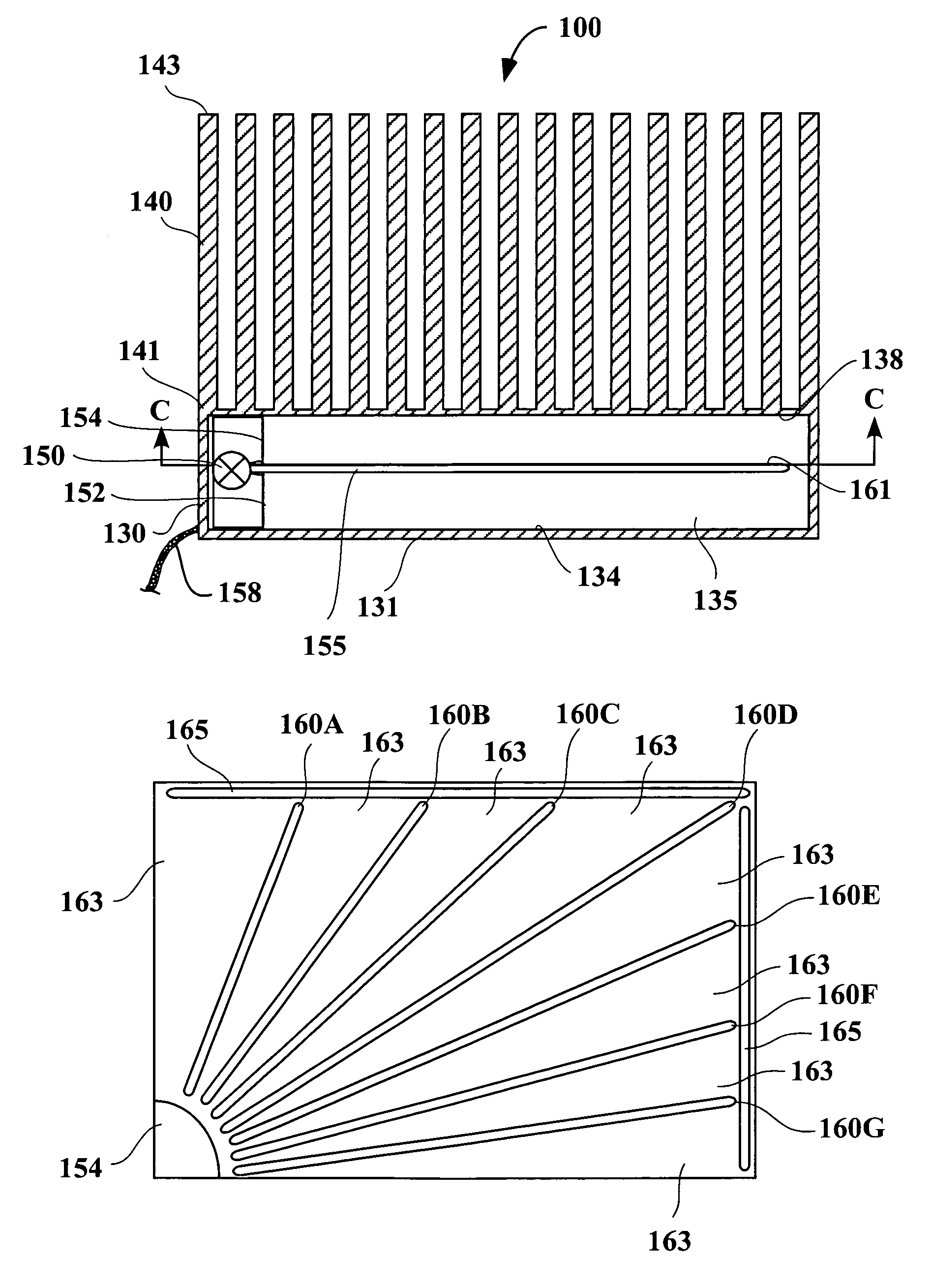
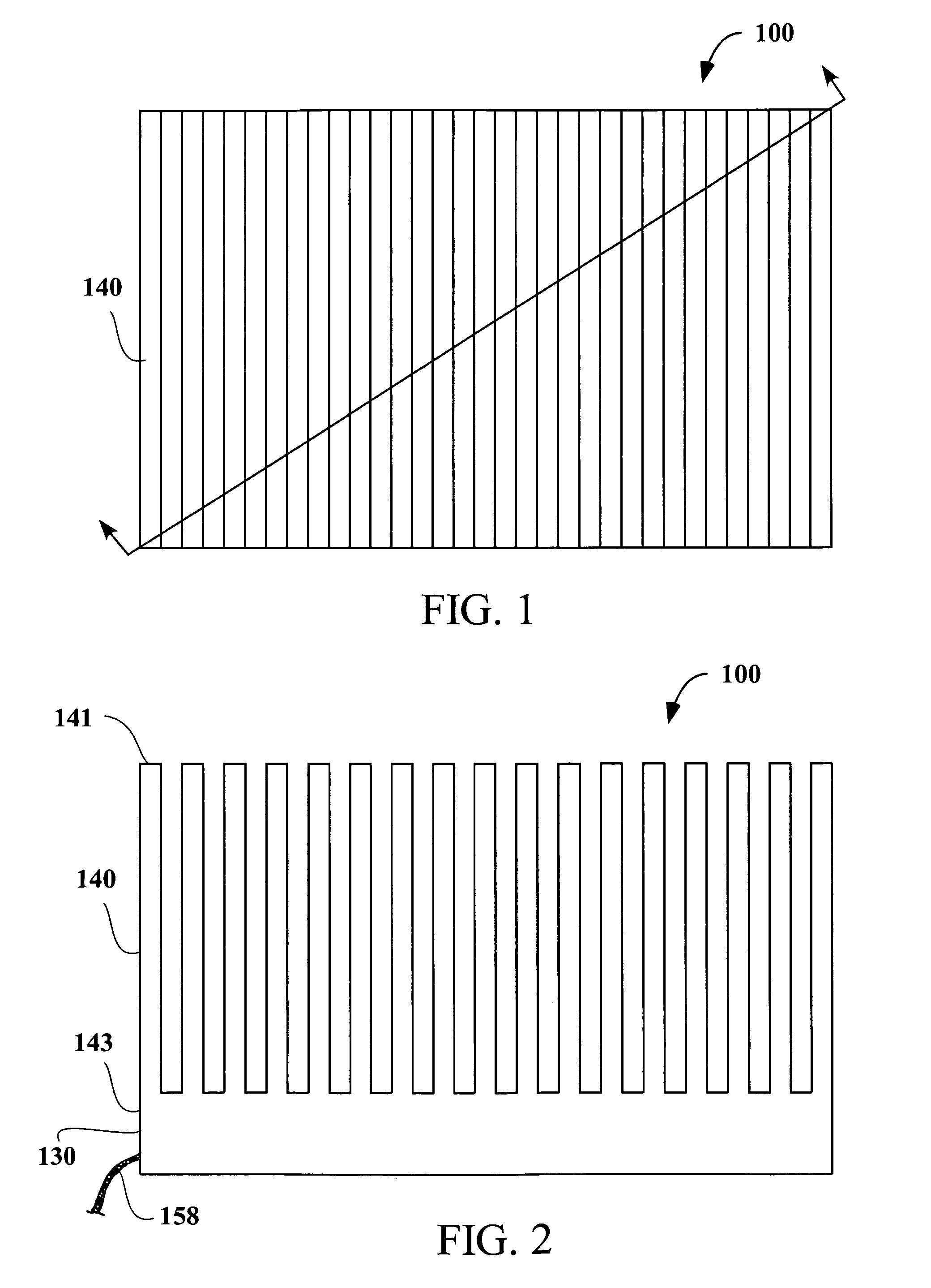
[0024]Referring now to FIGS. 1 and 2 there is shown a top view and a side view of heatsink 100. Heatsink 100 includes a plurality of fins 140 extending from base 130. Fins 140 further include first end 141 and second end 143. In one embodiment, first end 141 of fins 140 is fixedly attached to base 130. In a preferred embodiment, fins 140 are integrated with base 130. Heatsink 100 may be constructed of any material having good thermodynamic properties such as steel, stainless steel, aluminum, magnesium, copper or any other similar material.

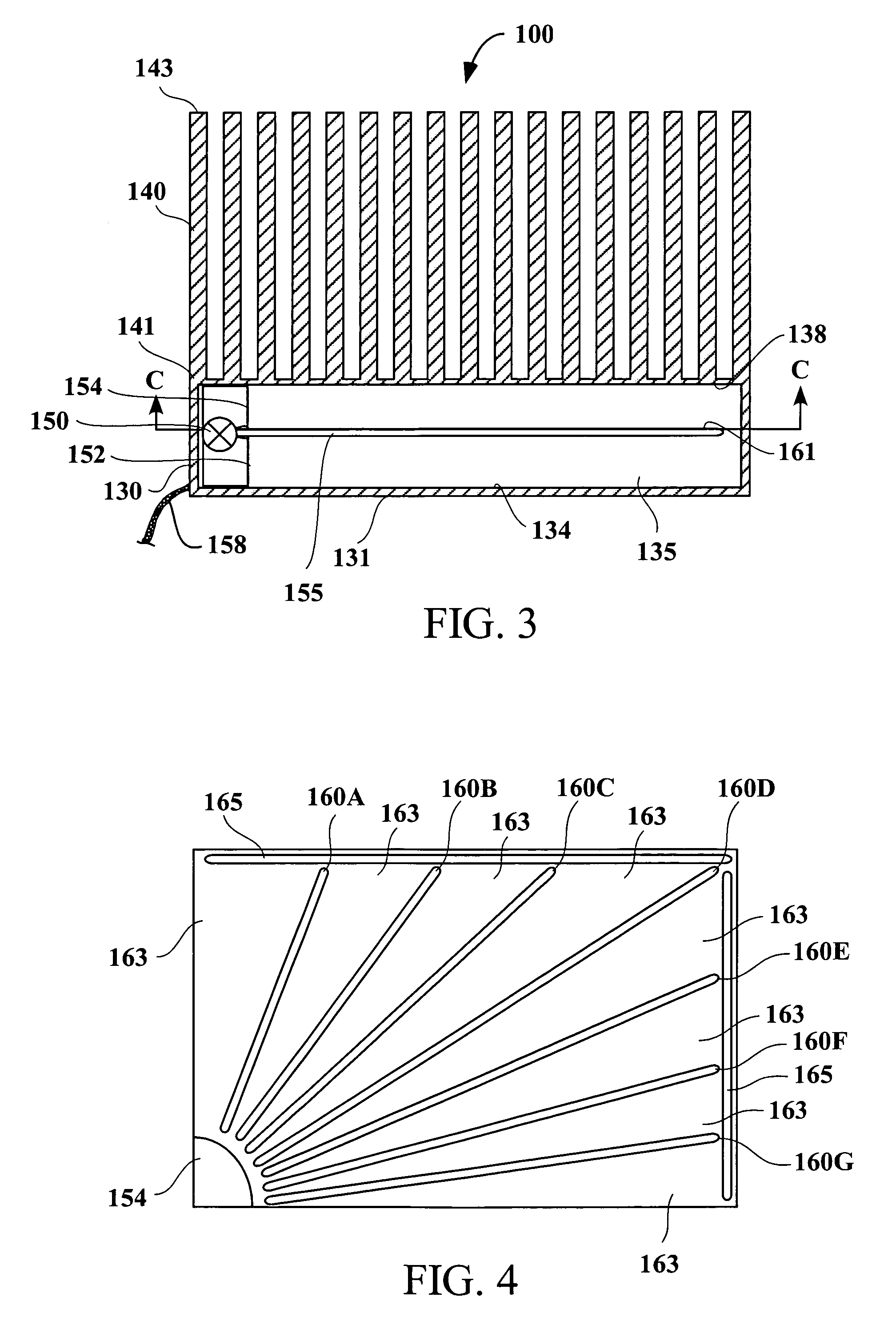
[0025]Referring now to FIG. 3, there is shown a cross-sectional view of heatsink 100. As shown in FIG. 3, base 130 further includes chamber 135 defined by a first surface 134 and a second surface 138. Chamber 135 is further defined by divider 155 disposed between first surface 134 and second surface 138 of chamber 135. Chamber 135 further includes pump 150, pump inlet 152 and pump outlet 154, cooling fluid 170, flow divider 160a through 160g, and f...


PUM


Abstract

A device for the transfer of heat away from a heat source comprising a base having first and second surfaces a plurality of fins extending adjacent to the second surface of the base. The base further including a chamber disposed between the first surface and the second surface of the base. The chamber further including a divider disposed therein adjacent the first surface. A pump is also disposed within the chamber to circulate fluid within the chamber.

Description

FIELD OF THE INVENTION[0001]The present invention relates to heatsinks for integrated circuits, more specifically an improved heat sink for central processing units (CPUs).[0002]Prior Art[0003]One side-effect of integrated circuits is that during use, some of the energy that is consumed is expelled as heat. Thus, there became a requirement to cool the integrated circuit during use. The problem of excessive heat buildup within integrated circuits has been a design consideration with which designers have had to contend with as the chips which house the integrated circuits are made smaller.[0004]Designers have attempted to address the problem in many different ways. In one embodiment, a fan may be installed in the enclosure where the circuits reside, thereby constantly circulating air within the enclosure and over the chips to remove the excessive heat through the use of convection. Although this method is effective and relatively inexpensive to implement there are shortcomings associa...

Claims


Application Information

Patent Timeline
Patent Type & Authority Patents(United States)
IPC IPC(8): F28F7/00F28D15/00F28F3/04F28F27/02H01L23/467H01L23/473
CPCF28D15/00F28F3/04F28F9/0265H01L23/467H01L23/473H01L2924/0002H01L2924/00
Inventor GEKTIN, VADIMNOVOTNY, SHLOMOVOGEL, MARLIN R.
Owner ORACLE INT CORP
Why Eureka
Try Eureka