Symmetrical heat sink module with a heat pipe for spreading of heat

Inactive Publication Date: 2005-09-20
DATECH TECH CO LTD
View PDF8 Cites 75 Cited by
  • Summary
  • Abstract
  • Description
  • Claims
  • Application Information

AI Technical Summary

Benefits of technology

[0005]Therefore, the main purpose of the present invention is to form a first set of fins and a second set of fins to be

Problems solved by technology

Although the prior art mentioned above is able to dissipate heat by a heat sink module, the heat sink module is formed as a unity with limited di

Method used


Image

  • Symmetrical heat sink module with a heat pipe for spreading of heat
  • Symmetrical heat sink module with a heat pipe for spreading of heat
  • Symmetrical heat sink module with a heat pipe for spreading of heat

Examples


Example

[0015]The following descriptions of the preferred embodiments are provided to understand the features and the structures of the present invention.

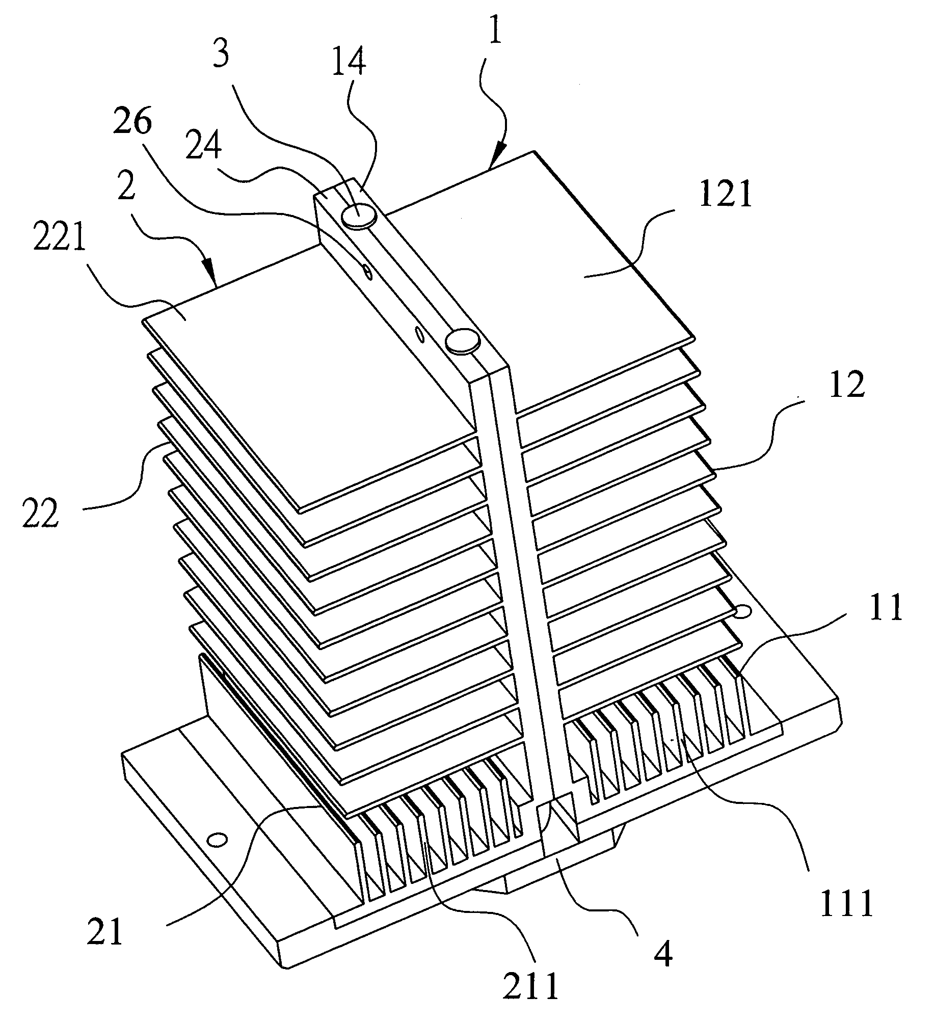
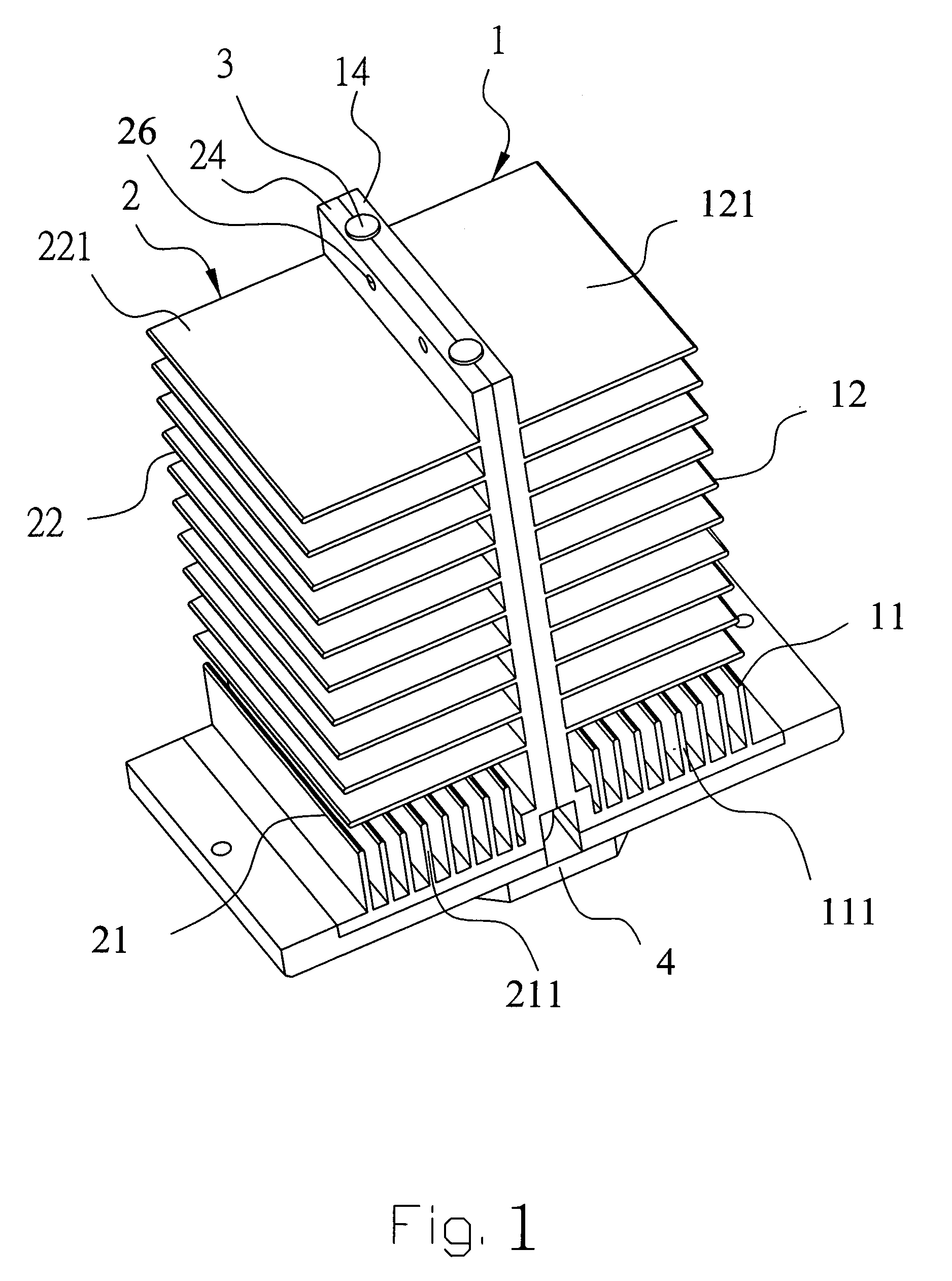
[0016]Please refer to FIG. 1 through FIG. 3, which are a perspective view, an exploded view showing the structure and a side view, according to an embodiment of the present invention. As shown in the figures, the present invention is a symmetrical heat sink module with a heat pipe for spreading of heat, comprising a first set 1 of fins, a second set 2 of fins. a heat pipe 3 and a base 4. The first and the second sets 1,2 of fins are made of alumni, copper, alumni alloy or copper alloy which has better heat dissipation capability.

[0017]The first set 1 of fins comprises a first dissipation area 11 at the bottom, which is extended up from the bottom toward an end. A second dissipation area 12 is on a surface of the first set 1 of fins near the first dissipation area 11 extended outwardly from the surface of the first set 1 of fins. The first ...


PUM


Abstract

The present invention is a symmetrical heat sink module with a heat pipe for spreading of heat, comprising a first and a second sets of fins each with a first and a second heat dissipation areas where the first and the second heat dissipation areas each comprises corresponding concave parts; a curved heat pipe between the concave parts with the bottom being convex out of the bottom of the first and the second sets of fins; and a base at the convex bottom of the curved heat pipe. Accordingly, the first and the second sets of fins are corresponding to each other so that the heat sink module obtains larger heat dissipation area and the function of two-side dissipation to achieve better heat dissipation efficiency.

Description

FIELD OF THE INVENTION[0001]The present invention relates to a heat sink module; more particularly, relates to forming two symmetrical sets of fins in the module to get larger heat dissipation area and to dissipate heat at both sides so that a better heat dissipation efficiency is achieved.DESCRIPTION OF THE RELATED ART[0002]The prior art of “Heat sink apparatus” as disclosed in U.S. Pat. No. 6,525,939 comprising: a fan comprising at least one attachment hole; a heat sink module mounted on the CPU, comprising a metal heat conduction column, a plurality of arc-shaped cooling fins radiating from the edge of the metal heat conduction column and a plurality of mounting holes positioned at the ends of the arc-shaped cooling fins, corresponding to the attachment holes; and a latch comprising a latch arm, a plurality of openings and at least one latch hole.[0003]Therein, the latch arm is secured to the socket of the CPU; each of the openings correspond to the mounting holes and the attachm...

Claims


Application Information

Patent Timeline
IPC IPC(8): F28D15/00F28D15/02F28F1/32H01L23/427H01L23/467
CPCF28D15/0275F28F1/32H01L23/427H01L23/467H01L2924/0002H01L2924/00F28F3/02
Inventor LI, NIEN-LUNHSU, TOLEE, CHENG-HSINGCHU, HUNG-CHUNG
Owner DATECH TECH CO LTD
Why Eureka
Try Eureka