Optical unit and projection type projector apparatus using the same

a projection device and optical unit technology, applied in the field of projection device and projection type projector apparatus, can solve the problems of inability to obtain fine spectral transmission factor performance, disadvantageous size, weight and cost scheme, etc., and achieve the effect of low cos

Inactive Publication Date: 2005-09-20
MAXELL HLDG LTD
View PDF4 Cites 4 Cited by
  • Summary
  • Abstract
  • Description
  • Claims
  • Application Information

AI Technical Summary

Benefits of technology

[0010]An object of the present invention is to make a polarization state of a beam incident on a reflection type liquid crystal panel the same as a polarized state of a reflected ON beam supplied from the reflection type liquid crystal panel in a configuration using a cross prism having a dichroic function and the reflection type liquid crystal panel, and thereby provide a small-sized, light-weighted, low cost illumination apparatus, and a projection type projector apparatus using the illumination apparatus.

Problems solved by technology

As a result, fine spectral transmission factor performance cannot be obtained.
Thus, this scheme is disadvantageous in size, weight and cost.

Method used


Image

  • Optical unit and projection type projector apparatus using the same
  • Optical unit and projection type projector apparatus using the same
  • Optical unit and projection type projector apparatus using the same

Examples


first embodiment

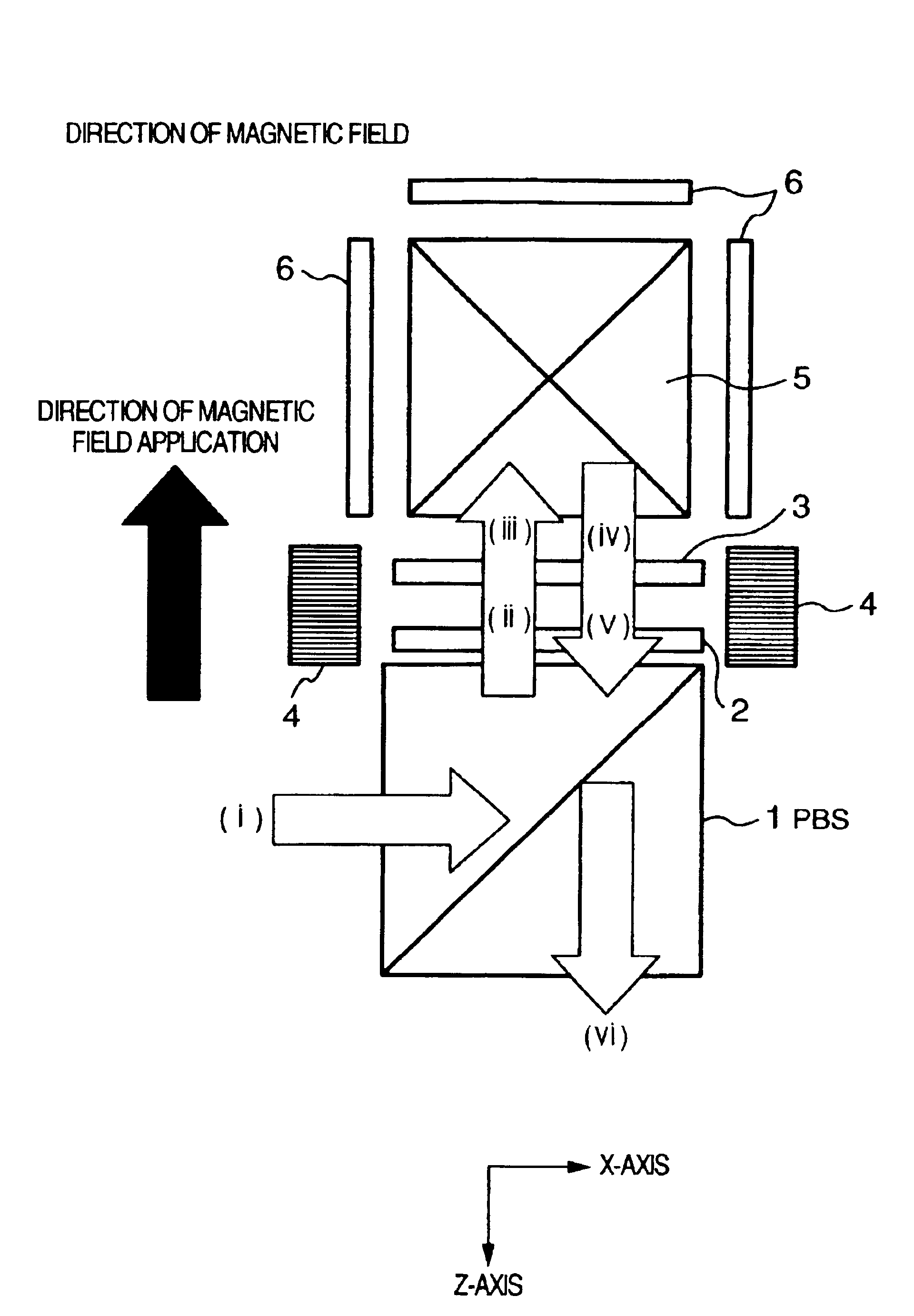
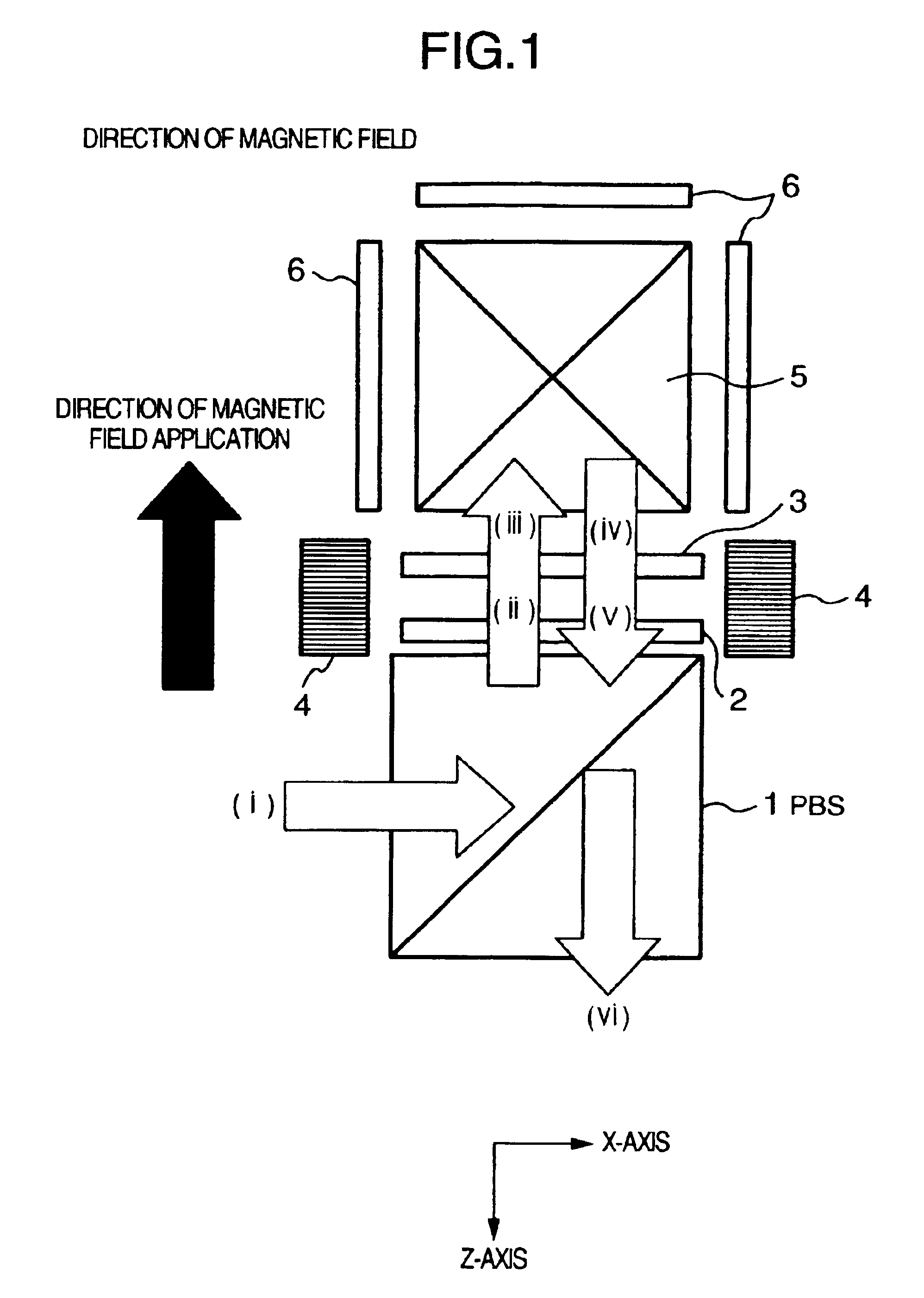
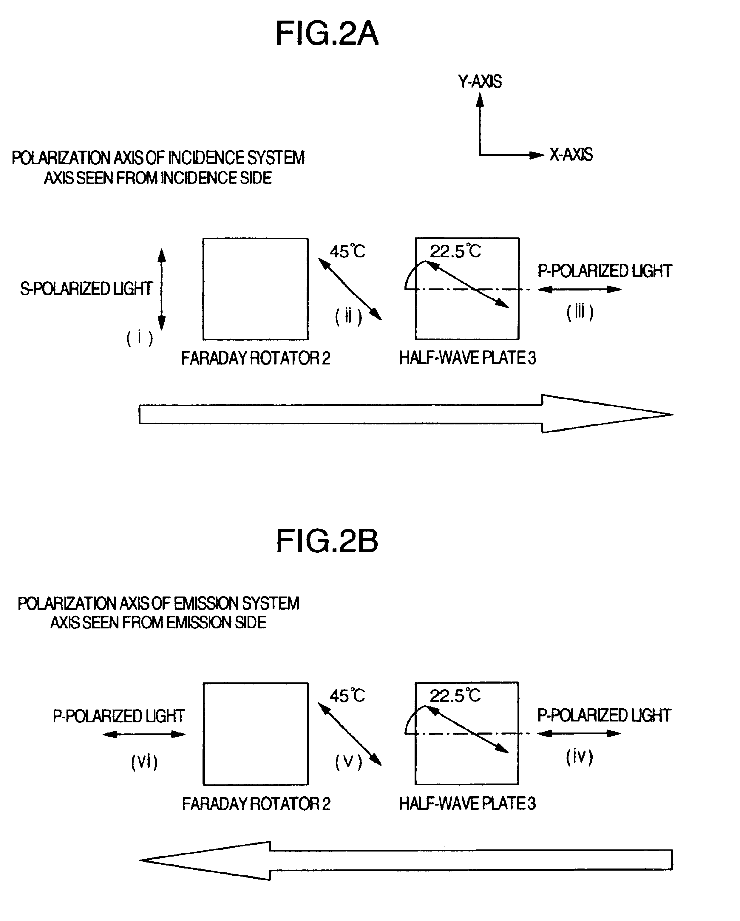
[0026]FIGS. 1, 2A, 2B and 3 are diagrams of the present invention. FIG. 1 is a basic configuration diagram of a color separation and synthesis section included in a projection type projector apparatus. FIGS. 2A and 2B are diagrams showing details of polarization states of a beam. FIG. 3 is a diagram showing a general configuration of an optical system of a projection type projector apparatus using a color separation and synthesis section shown in FIG. 1.

[0027]In FIG. 1, reference numeral 1 denotes a PBS having a function of reflecting S-polarized light and transmitting P-polarized light and making it go straight on. Numeral 2 denotes a Faraday rotator including a garnet crystal plate. Numeral 3 denotes a half-wave plate having a polarization axis for rotating incident linearly polarized light by 45 degrees. Numeral 4 denotes a magnet for providing the Faraday rotator with a constant direction of magnetic field application, 5 a cross prism having a dichroic function, and 6 a reflecti...

second embodiment

[0044]the present invention will now be described with reference to FIGS. 5 and 6. FIG. 5 is a basic configuration diagram of a color separation and synthesis section of a projection type projector apparatus. FIGS. 6A and 6B are diagrams showing details of beam polarization states.

[0045]In FIG. 5, an incident beam aligned in polarization state with S-polarized light ((i)) is input to the PBS 1. The S-polarized light is reflected by the PBS plane of the PBS 1 toward the cross prism 5, and input to the half-wave plate 3. Linearly polarized light ((ii)) obtained by rotating the linearly polarized light by 45 degrees in the half-wave plate 3 is then further rotated by 45 degrees in the Faraday rotator 2 to become P-polarized light ((iii)). White light with P-polarization incident on the cross prism 5 is separated into three colors R, G and B by the dichroic function of the cross prism 5, and R, G and B beams are reflected respectively by the reflection type liquid crystal panels 6 corre...

third embodiment

[0057]In order to superpose light quantity distributions of respective lens surfaces included in the integrator 13 on the reflection type liquid crystal panels 6, optical mapping relations between the polarization conversion element 14 and the reflection type liquid crystal panels 6 must be maintained. Therefore, the polarization direction of the polarization conversion element 14 and the polarization direction of the cross prism 5 also become the same. On the other hand, since there is a difference of 45 degrees between the polarization direction of the cross prism 5 and the polarization direction of the PBS 1, there is also a difference of 45 degrees between the polarization direction of the polarization conversion element 14 and the polarization direction of the PBS 1. In the present invention, therefore, it is necessary to dispose a half-wave plate for rotating the polarization direction of linearly polarized light by 45 degrees and generating S-polarized light for the PBS 1, on...


PUM

PropertyMeasurementUnit
angleaaaaaaaaaa
angleaaaaaaaaaa
Faraday rotation angleaaaaaaaaaa

Abstract

By making the beam polarization state in a cross prism having a dichroic function for an incident beam on a reflection type liquid crystal panel the same as that for a reflected ON beam, a small-sized, low cost projection type projector apparatus is provided. A Faraday rotator having a Faraday rotation angle of 45 degrees is disposed on an optical path between a PBS and a cross prism. A half-wave plate having such a polarization axis as to rotate a polarization angle of linearly polarized light by 45 or 135 degrees is disposed on an optical immediately before or behind the Faraday rotator.

Description

CROSS-REFERENCE TO RELATED APPLICATIONS[0001]This application is a continuation application of U.S. patent application Ser. No. 10 / 356,000, filed Jan. 31, 2003, now U.S. Pat. No. 6,832,836, and titled “Optical Unit and Projection Type Projector Apparatus Using the Same,” which is related to and claims priority from Japanese Patent Application 2002-048938, filed Feb. 26, 2002, and is herein incorporated by reference for all purposes.BACKGROUND OF THE INVENTION[0002]The present invention relates to a projection type projector apparatus using a reflection type liquid crystal panel, such as a so-called liquid crystal projector or projection type television using forward projection.[0003]Liquid crystal projectors for business use have widely spread. Furthermore, as a substitute for a conventional image display apparatus of such a scheme that an image displayed on a cathode-ray tube is projected onto a screen, development of a projection type television using liquid crystal display elemen...

Claims


Application Information

Patent Timeline
Patent Type & Authority Patents(United States)
IPC IPC(8): G02B27/28H04N9/31G02F1/13G02F1/1335G03B21/00
CPCG02B27/283H04N9/3105H04N9/3197G03B21/00
Inventor YATSU, MASAHIKOHIRATA, KOJIYAMASAKI, FUTOSHI
Owner MAXELL HLDG LTD
Why Eureka
Try Eureka