Rotor blade

Inactive Publication Date: 2005-09-20
WOBBEN ALOYS
View PDF16 Cites 5 Cited by
  • Summary
  • Abstract
  • Description
  • Claims
  • Application Information

AI Technical Summary

Benefits of technology

[0007]The object of the invention is to better integrate a wind power installation into the landscape view, to improve environmental compatibility and

Problems solved by technology

Admittedly, society accepts and welcomes the fact that wind power installations are used, because power can be very effectively produced therewith by a regenerative pr

Method used


Image

  • Rotor blade
  • Rotor blade
  • Rotor blade

Examples


Example

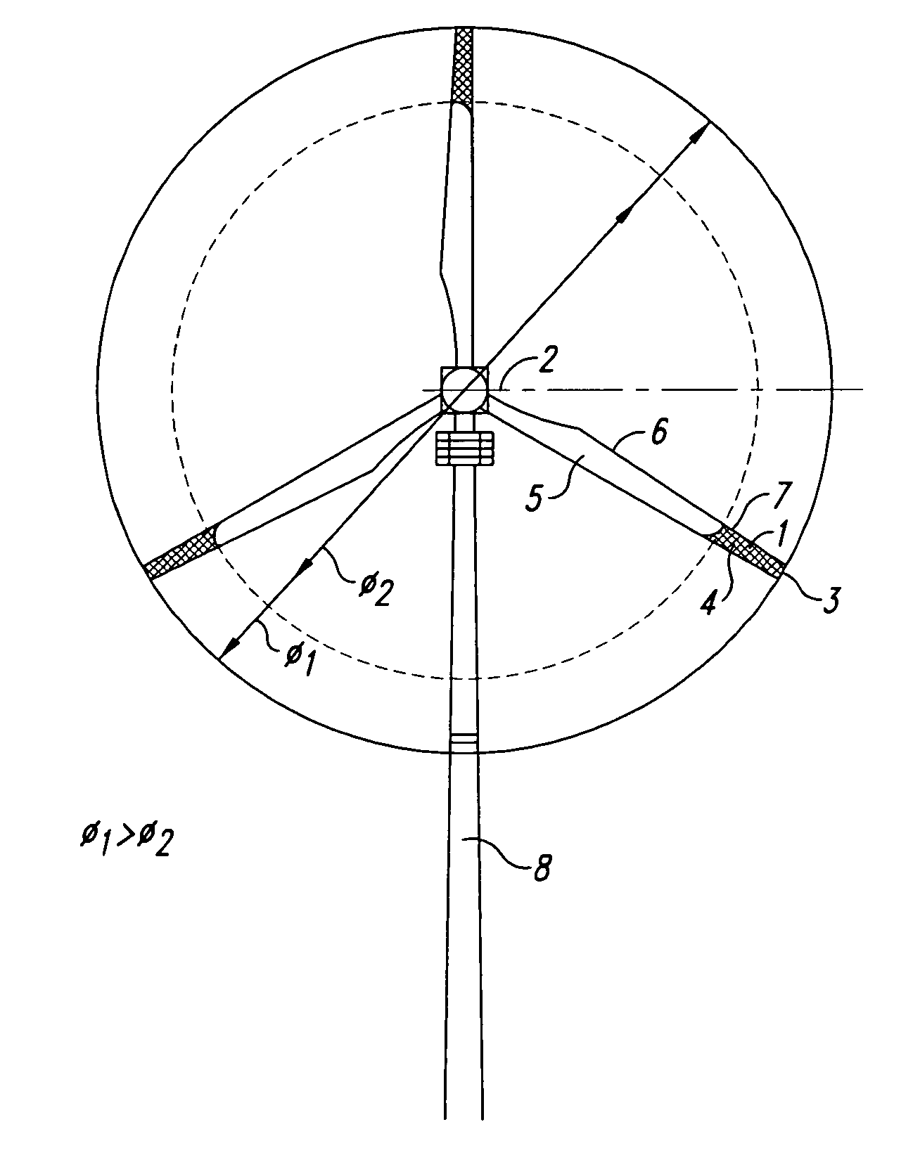
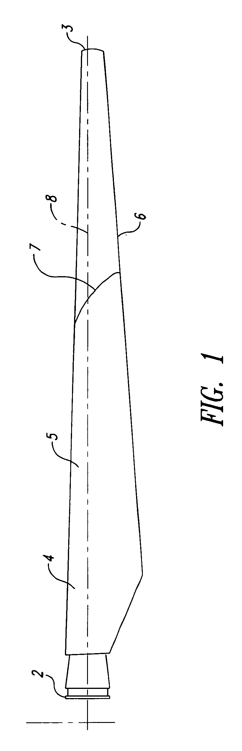
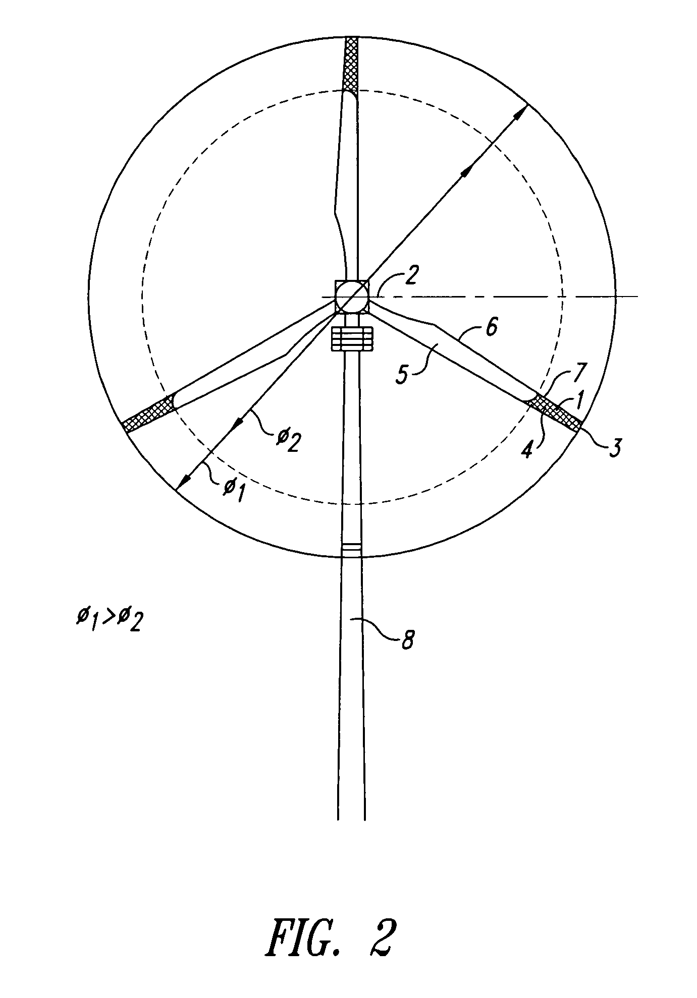
[0013]FIG. 1 is a view of a rotor blade 1 with a rotor blade connection 2 at one end and a rotor blade tip 3 at the other end. The surface of the rotor blade on which the wind impinges (dynamic pressure surface) is divided into two regions 4, 5 which are of different colors, of which the region 5 which is associated with the rotor blade connection 2 is markedly lighter than the region 4 which is associated with the rotor blade tip 3. The darker one of the two regions is contained in particular in a gray, blue or gray / blue or in another daylight sky-colored or natural-colored or background-colored shade. In contrast to a known signal-red coating of paint on the tip region of the rotor blade, in the case of the rotor blade 1 according to the invention that region is precisely not optically clearly visible but in contrast is provided with a “quasi” camouflage color so that an individual rotor blade which rotates in a wind power installation with the rotor thereof is optically scarcely ...


PUM


Abstract

Rotor blades for wind power installations of varying design configurations are known. Irrespective of the geometrical configuration of the rotor blades, all rotor blades are generally of a uniform color; typically. The rotor blades of the present invention better integrate a wind power installation into the landscape view, to improve environmental compatibility and to reduce the impact of the foreign body. That is to be achieved in particular in respect of installations with large rotor diameters (more than 40 m). A rotor blade comprising a rotor blade connection and a rotor blade tip and a surface which is arranged therebetween and which is divided into at least two regions which differ in respect of lightness and of which the lighter region is arranged closer to the rotor blade connection than the darker region which is of a natural shade and/or daylight sky shade and/or background shade.

Description

BACKGROUND OF THE INVENTION[0001]1. Field of the Invention[0002]The invention concerns a rotor blade of a wind power installation and a wind power installation having such a rotor blade.[0003]2. Description of the Related Art[0004]Rotor blades of the most widely varying design configurations have already long been known. Known rotor blades can be made from various materials such as for example aluminum, titanium, steel, composite fiber material (glass, carbon or aramide fibers), wood and the like. Irrespective of the geometrical configuration of the rotor blade material however all rotor blades are generally of a uniform color. In that respect a white coat of paint is preferred.[0005]It is also known for a rotor blade to be provided with a signal-red coat of paint in the rotor blade tip region, which is required in particular when a wind power installation is located in the region of an airdrome or airport or a flight zone so that the wind power installation or the rotor blades can ...

Claims


Application Information

Patent Timeline
IPC IPC(8): F03D1/00F03D11/00F03D1/06B64C11/16F03D80/10F04D29/38
CPCF03D1/0633F03D11/0041Y02E10/721Y02E10/722F03D80/10Y02E10/72Y02P70/50F03D9/25F03D1/0675F05B2240/221
Inventor WOBBEN, ALOYS
Owner WOBBEN ALOYS
Why Eureka
Try Eureka