
Hybrid powertrain system

a hybrid powertrain and powertrain technology, applied in mechanical equipment, transportation and packaging, gearboxes, etc., can solve the problems of high torque, complex hardware and control systems for regenerative braking of vehicles, and low speed electric motors to match the relatively low speed of engines. achieve the effect of improving shift quality, enabling automatic power shifting of transmissions, and recovering energy

Inactive Publication Date: 2005-09-20
EATON CORP
View PDF19 Cites 52 Cited by
  • Summary
  • Abstract
  • Description
  • Claims
  • Application Information

AI Technical Summary

Benefits of technology

[0009]One feature of the present invention is that either one of the first and second prime mover driven countershafts may be selectively operated to maintain torque at the drive wheels of the vehicle while the other prime mover driven countershaft is undergoing a gear interchange with the main shaft. This feature advantageously improves shift quality and enables automated power shifting of the transmission. Another feature of the present invention is that the second prime mover is operable to provide the sole power to launch and propel the vehicle without a main clutch. The second prime mover is also operable to supply the sole driving power during reverse operation of the vehicle, thereby eliminating the need for a reverse idler gear in the transmission. Furthermore, the power output of the second prime mover and the first prime mover may be combined to drive the vehicle.

Problems solved by technology

Another limitation of this type of parallel hybrid powertrain system is that it requires a high torque, low speed electric motor to match the relatively low speed of the engine.
A limitation of this type of powertrain system is that the output torque of the engine and motor must be precisely controlled to balance one another during steady state operation.
Another limitation of this type of powertrain system is that regenerative braking of the vehicle requires complex hardware and control systems.

Method used


Image

  • Hybrid powertrain system
  • Hybrid powertrain system
  • Hybrid powertrain system

Examples


Embodiment Construction

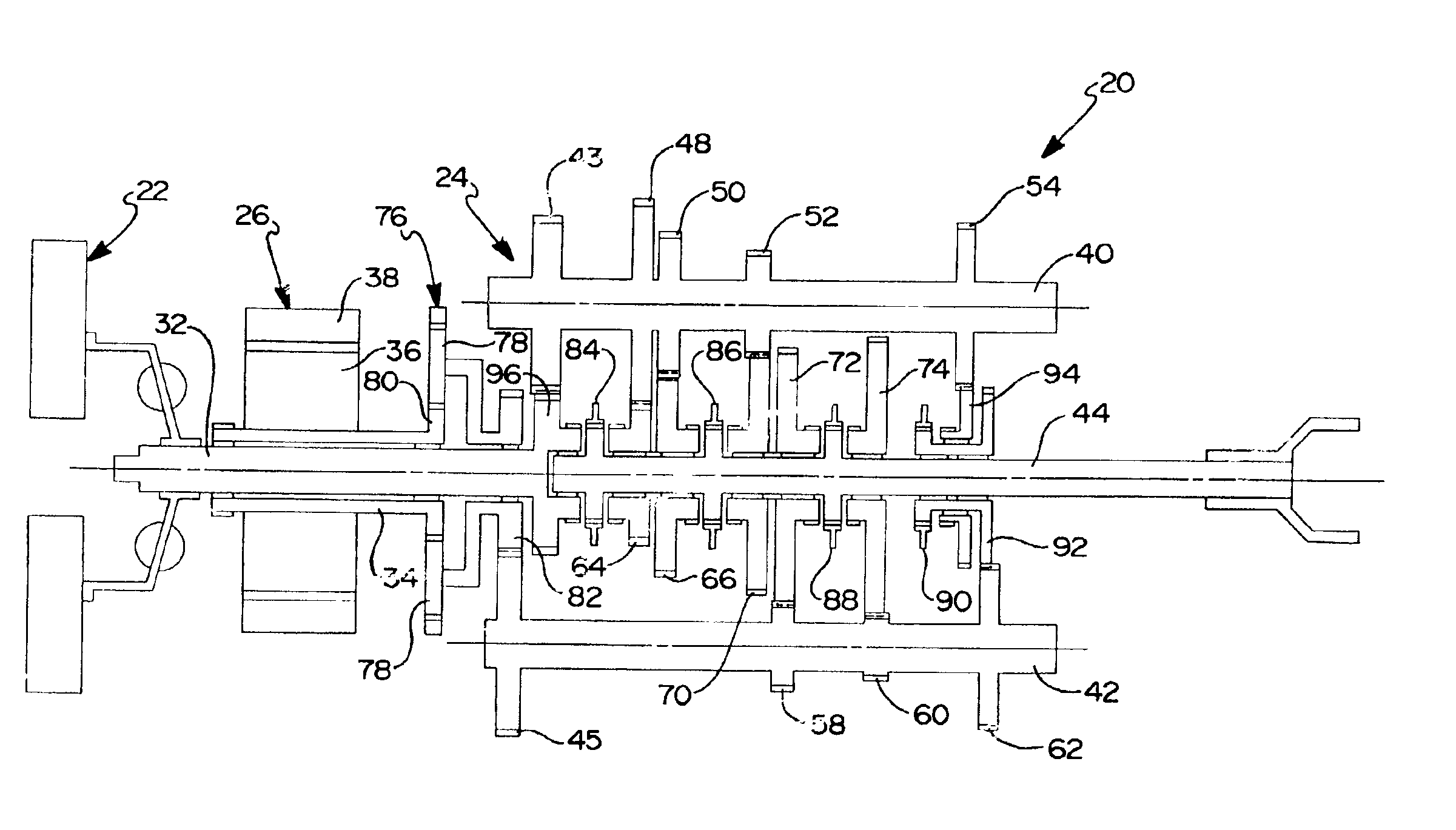
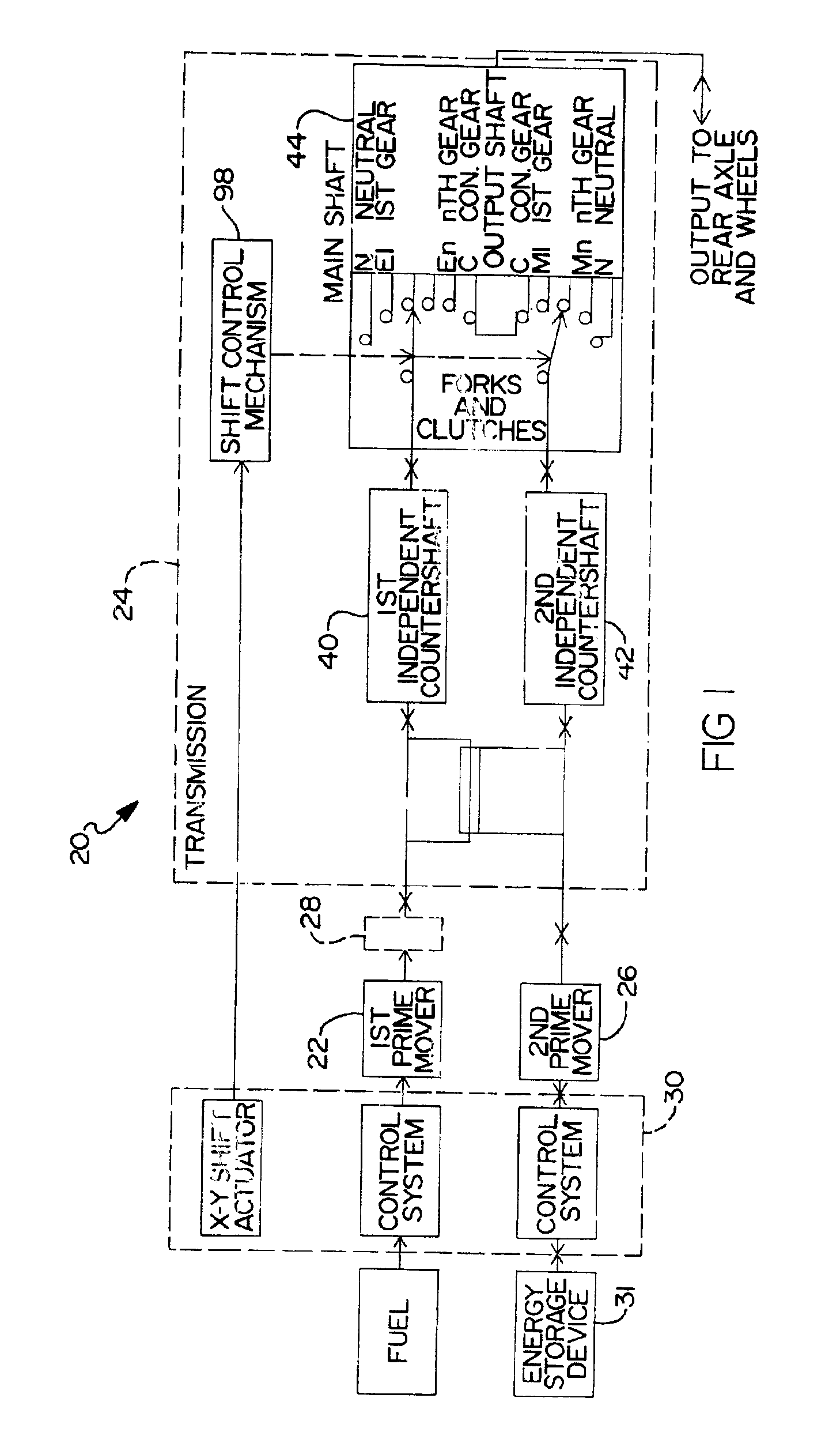
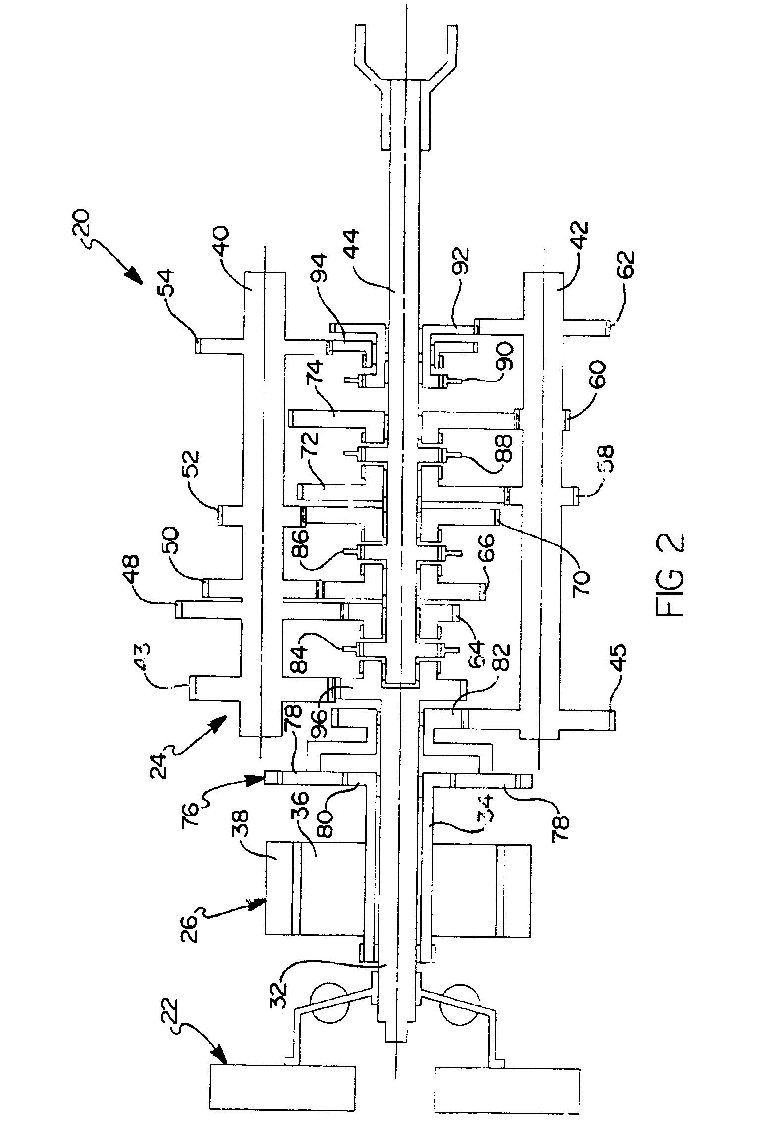
[0025]Referring now to the drawings, the preferred embodiments of the present invention are shown in detail. Referring to FIG. 1, a hybrid powertrain system 20 is provided that includes a first prime mover 22, such as a spark-ignited or compression-ignited internal combustion engine, a change-gear transmission 24 and a second prime mover 26, such as an electric motor / generator or a hydraulic motor / pump. Optionally, hybrid powertrain system 20 may be provided with a main clutch 28 (shown in phantom), such as a master friction clutch, which can be selectively operated to disengage first prime mover 22 from transmission 24.

[0026]An electronic control unit (ECU) 30 is incorporated into powertrain system 20 to provide control for first prime mover 22, second prime mover 26 and transmission 24. ECU 30 preferably includes a conventional programmable digital computer (not shown) that is configured to receive various input signals, including, but not limited to, the operating speeds of first...


PUM


Abstract

A hybrid powertrain system is provided that includes a first prime mover having a rotational output, a second prime mover having a rotational output, and a transmission having a main shaft supporting at least two main shaft gears thereon. The transmission includes a first independent countershaft drivingly connected to the first prime mover and including at least one ratio gear supported thereon that meshes with a respective main shaft gear. A second independent countershaft is drivingly connected to the second prime mover and includes at least one ratio gear supported thereon that meshes with a respective main shaft gear. The ratio gears on the first and second countershafts cooperate with the main shaft gears to provide at least one gear ratio between the first and second countershafts and the main shaft. A shift control mechanism selectively engages and disengages the first and second countershafts for rotation with the main shaft.

Description

[0001]This invention was made with Government support under NREL Subcontract No. ZCL-2-32060-01, Prime Contract DE-AC36-99 GO10337 awarded by the Department of Energy. The government has certain rights in this invention.BACKGROUND OF THE INVENTION[0002]1. Field of the Invention[0003]The present invention relates generally to powertrain systems and, more particularly, to a hybrid powertrain system employing at least two prime movers and a dual independent countershaft transmission.[0004]2. Description of the Related Art[0005]Hybrid vehicle powertrain systems employing two or more prime movers to drive the vehicle are well known in the art. Previous hybrid powertrain systems have utilized an internal combustion engine that is strategically operated in combination with an electric motor to provide driving torque to the wheels of the vehicle.[0006]So-called “parallel hybrid” powertrain systems have been developed that commonly interface the electric motor in line between the vehicle eng...

Claims


Application Information

Patent Timeline
IPC IPC(8): B60K6/04B60K6/00F16H3/08F16H63/08F16H63/20F16H3/097F16H61/688F16H61/68B60K6/36B60K6/365B60K6/48B60K6/547B60W10/115F16H3/093
CPCB60K6/547F16H3/097B60K6/36B60K6/365B60K6/48F16H63/20B60K2741/105F16H37/065F16H61/688Y10T74/19135Y02T10/6221Y10T74/19233B60W10/115B60W20/00Y02T10/62
Inventor GRILLO, RICARDO C.O'NEIL, WALTER K.PRESTON, DAVID M.
Owner EATON CORP
Learn More