Photomultiplier

a photomultiplier and tube technology, applied in the field of photomultiplier tubes, can solve the problems of poor pulse linearity, easy to achieve the unsatisfactory space charge effect, and difficult to manufacture a photomultiplier tube compact in size with the capacity to withstand vibrations

Inactive Publication Date: 2005-09-20
HAMAMATSU PHOTONICS KK
View PDF12 Cites 13 Cited by
  • Summary
  • Abstract
  • Description
  • Claims
  • Application Information

AI Technical Summary

Benefits of technology

[0022]By forming the third and fifth dynodes similar to the second dynode, the third and fifth dynodes being smaller than the second dynode, the same effects as that of when the secondary electron surfaces of the third and fifth dynodes are made in order to have only a curved surface with an arcuate cross-section can be attained.
[0023]In the photomultiplier tube of the present invention, it is possible to provide a shielding plate between the first dynode and the (n−3)th through nth dynodes.
[0024]This construction can prevent light and ions generated when electrons collide with the (n−3)th through nth dynodes from traveling toward the photocathode.

Problems solved by technology

Accordingly, an undesirable space charge effect can easily occur.
The circular cage type electron multiplying unit construction disclosed in Japanese unexamined patent application publication 2-291655 has poor pulse linearity due to the problems of the space charge effect and the weak electric field intensity.
These box-shaped dynodes have a large and complex construction including a box-type secondary electron emitting unit and a grid, making it difficult to manufacture a photomultiplier tube that is compact in size with a capacity to withstand vibrations.
Further, the travel time of the electrons increases among these box-type dynodes, resulting in an insufficient time response.

Method used


Image

  • Photomultiplier
  • Photomultiplier
  • Photomultiplier

Examples


Embodiment Construction

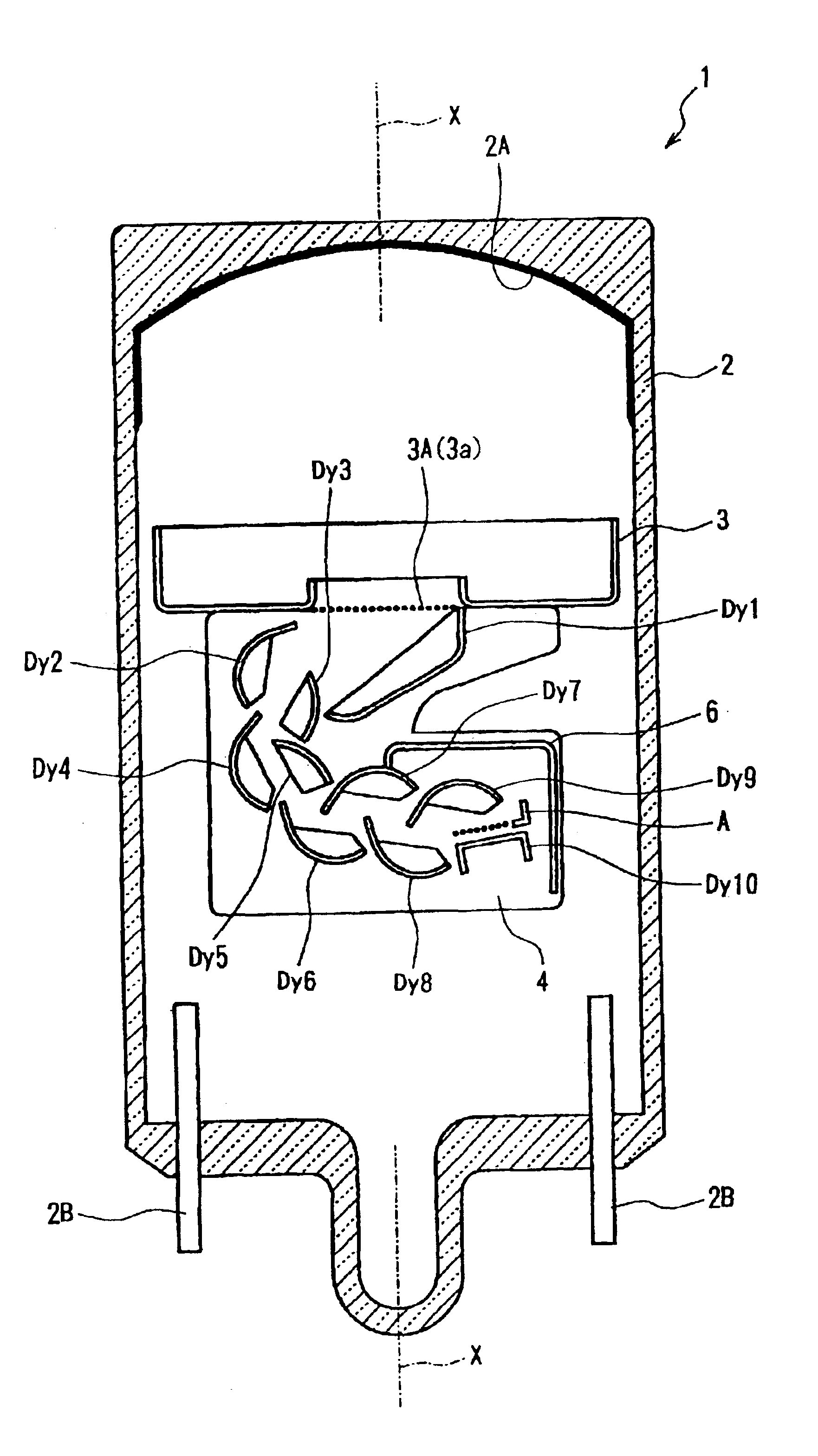
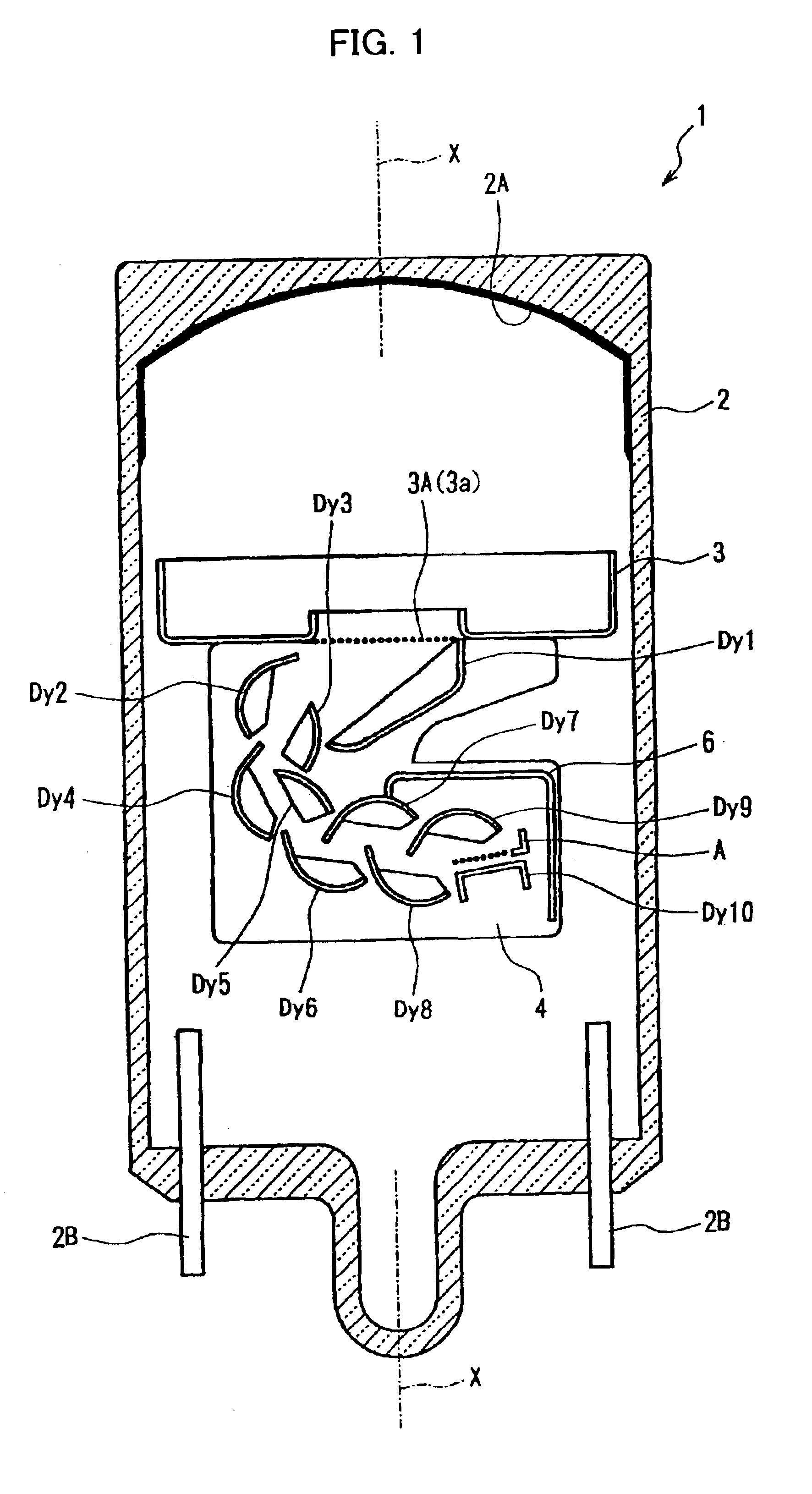
[0032]A photomultiplier tube according to a preferred embodiment of the present invention will be described based on FIGS. 1-6. A photomultiplier tube 1 according to the preferred embodiment includes a tube-shaped vacuum vessel 2 having a tube axis X. FIG. 1 is a cross-sectional view of the photomultiplier tube 1 cut along the tube axis X. The tube-shaped vacuum vessel 2 is formed from a material such as Kovar glass.

[0033]Both ends of the tube-shaped vacuum vessel 2 along the tube axis X are closed. The one end has a planar shape. A photocathode 2A is formed on an inner surface of this planar end for emitting electrons in response to incident light. The photocathode 2A is formed by reacting an alkali metal vapor with antimony that has been pre-deposited on the inner surface of the end. A plurality of lead pins 2B are provided on the other end of the tube-shaped vacuum vessel 2 for applying predetermined potentials to dynodes Dy1-Dy10 and an anode A. FIG. 1 shows only two of the lead...


PUM


Abstract

A photomultiplier excellent in vibration resistance and improved in pulse linearity characteristic and time-response. The fourth, and sixth to ninth dynodes (Dy4, Dy6 to Dy9) have a similar shape to that of the second dynode (Dy2). The third and fifth dynodes (dy3, Dy5) are smaller than the dynode (Dy2). The first to tenth dynodes (Dy1 to Dy10) are so arranged that the dynode inner space path defined between opposed dynodes is perpendicular to the tube axis (X). The anode (A) is a mesh anode (A), and is opposed to the dynode (Dy2) with respect to the tube axis (X).

Description

[0001]This application is a 371 application of PCT / JP01 / 06279, filed Jul. 19, 2001.TECHNICAL FIELD[0002]The present invention relates to a photomultiplier tube, and particularly to a photomultiplier tube with excellent vibration resistance and improved pulse linearity characteristics and time response.BACKGROUND ART[0003]Japanese unexamined patent application publication 2-291655 discloses a photomultiplier tube having a circular cage type electron multiplying unit. In the circular cage type electron multiplying unit, a path formed in the spaces between opposed dynodes traces a circle around an axis orthogonal to the tube axis. The second dynode and the anode are positioned on opposing ends in relation to the tube axis. Accordingly, the photomultiplier tube can be contracted in its axial direction, reducing the overall size of the tube construction.[0004]In order to form a circular path in the spaces between opposed dynodes, concave dynodes are positioned on the outer side of the pa...

Claims


Application Information

Patent Timeline
Patent Type & Authority Patents(United States)
IPC IPC(8): H01J43/00H01J43/18H01J43/20
CPCH01J43/18
Inventor KIMURA, SUENORIFURUHASHI, MASAMIISHIZU, TOMOHIROITO, MASUO
Owner HAMAMATSU PHOTONICS KK
Why Eureka
Try Eureka