Configurable feedback path in an amplitude control system

Inactive Publication Date: 2005-09-20
AGILENT TECH INC +1
View PDF5 Cites 3 Cited by
  • Summary
  • Abstract
  • Description
  • Claims
  • Application Information

AI Technical Summary

Benefits of technology

[0009]A configurable feedback path constructed according to the preferred embodiment of the present invention is included in an amplitude control system of a signal generator having a signal source and an amplitude controller. The configurable feedback path provides accurate tracking between a signal provided at a test port and a reference signal, whether or not an amplifier or other signal conditioner is coupled to the test port.
[0011]With the configurable feedback path arranged for an internally-leveled configuration of the amplitude control system, a first jumper couples the first access port to the second access port, and a second jumper couples the third access port to the fourth access port. The second jumper provides the signal from the signal source to the test port. The first jumper provides a coupled version of the signal from the signal source to the input of the detector. The detector generates a detected signal at the filtered output that corresponds to the amplitude of this coupled signal from the signal source. The amplitude controller receives the detected signal and sets the amplitude of the signal from the signal source in response to the detected signal. The detector also provides the coupled version of the signal from the signal source at the unfiltered output to provide the reference signal that accurately tracks the signal from the signal source provided to the test port via the second jumper.
[0012]With the configurable feedback path arranged for an externally-leveled configuration of the amplitude control system, a signal conditioner is coupled to the third access port, receiving the signal from the signal source. The signal conditioner provides a conditioned signal to a signal separator. A thru output of the signal separator is coupled to the fourth access port to provide the conditioned signal at the test port. A coupled output of the signal separator is coupled to the first access port, providing a coupled version of the conditioned signal to the input of the detector. The detector generates a detected signal at the filtered output that corresponds to the amplitude of the coupled conditioned signal. The amplitude controller receives the detected signal and sets the amplitude of the signal from signal source in response to the detected signal to establish the amplitude of the conditioned signal at the test port. The detector provides this coupled conditioned signal at the unfiltered output to provide the reference signal that accurately tracks the conditioned signal present at the test port.

Problems solved by technology

Non-linearities such as distortion, saturation or compression in the amplifier also result in amplitude changes at the output of the amplifier that do not correspond to changes in the amplitude of the signal 3, which makes it difficult to control the amplitude of the conditioned signal 7 at the output of the amplifier by adjusting the amplitude of the signal 3 provided at the input of the amplifier.
Further, in this internally-leveled configuration, the impedance match ZOUT presented to the DUT is determined primarily by the output impedance of the amplifier and does not benefit from an improved impedance match that would be provided to the DUT were the amplifier included within the feedback loop.
However, when the prior art amplitude control system is included in a signal generator for use with a network analyzer, the amplitude tracking error between the conditioned signal 7 at the output of the amplifier and the reference signal 9 still results due to the inherent non-linearities of the amplifier.
This amplitude tracking error that results in the externally-leveled configuration makes the prior art amplitude control system not well-suited for signal generators that are used with network analyzers.
These errors in amplitude settings result from the external detector having a transfer function that is generally different from the transfer function of the internal detector for which the amplitude controller 4 is calibrated.

Method used


Image

  • Configurable feedback path in an amplitude control system
  • Configurable feedback path in an amplitude control system
  • Configurable feedback path in an amplitude control system

Examples


Embodiment Construction

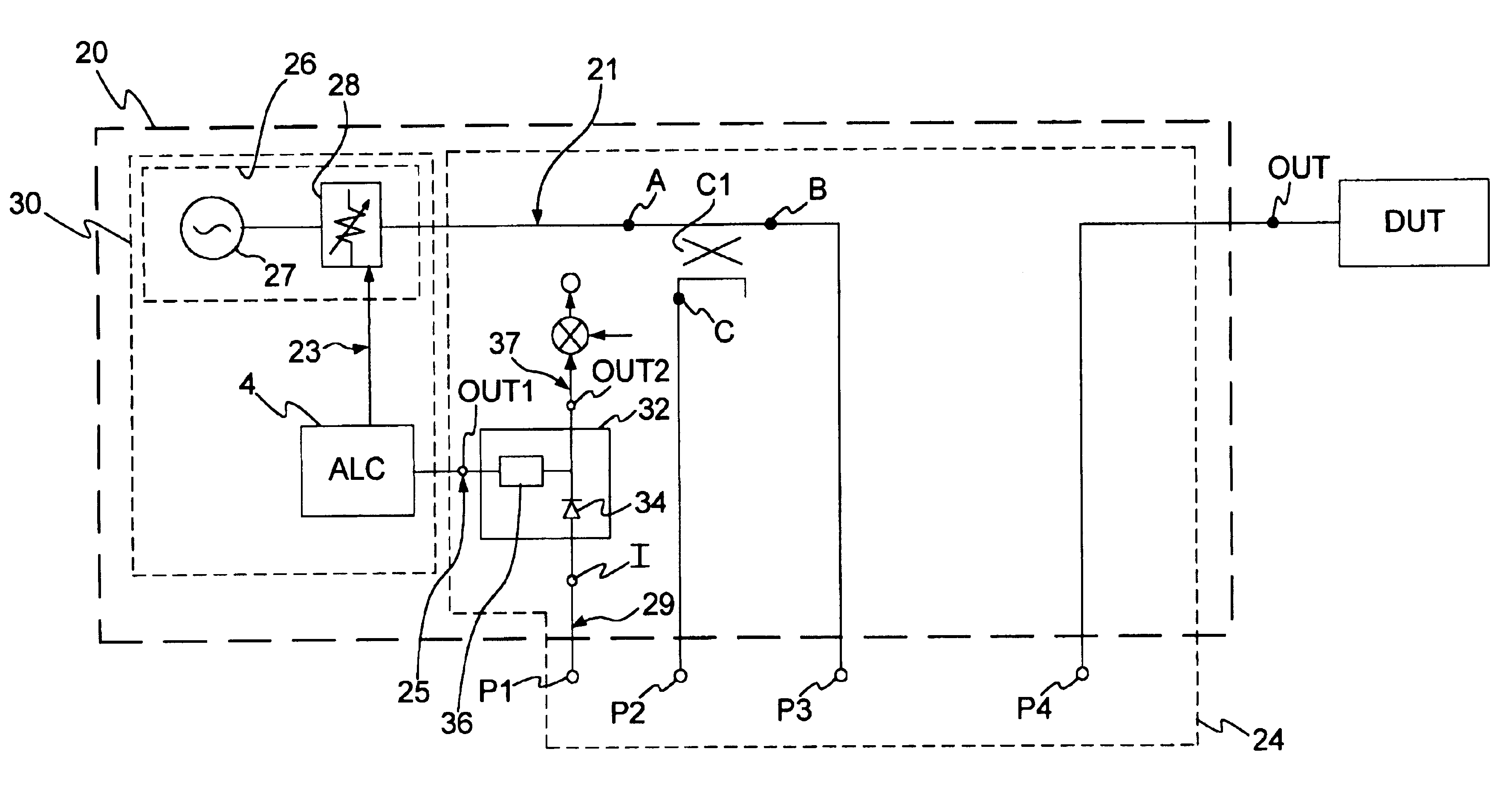
[0020]FIG. 2 shows a signal generator 20 including an amplitude control system having a configurable feedback path constructed according to the preferred embodiment of the present invention. The signal generator 20 is an instrument or system that provides electrical signals at a test port OUT. However, electrical-to-optical converters, piezo-electric devices or other signal transducers integrated with the signal generator 20 enable the signal generator 20 to process or accommodate signals that are optical, acoustical, or mechanical in nature. The signal generator 20 is a stand-alone instrument or system, or the signal generator 20 is integrated in, or used in conjunction with, other instruments or systems, such as network analyzers, spectrum analyzers, or other types of signal analyzers, signal processors, or signal measurement systems.

[0021]In addition to the test port OUT, the signal generator 20 that includes the configurable feedback path has a series of access ports. While four...


PUM


Abstract

A configurable feedback path is included in an amplitude control system having a signal source and an amplitude controller, and provides accurate tracking between a signal provided at a test port and a reference signal, whether or not the configurable feedback path is in an internally-leveled configuration or an externally-leveled configuration. The configurable feedback path includes a series of access ports, a detector that has an input coupled to the first access port, a filtered output coupled to the amplitude controller, and an unfiltered output providing the reference signal. The configurable feedback path also includes a signal separator that has an input terminal coupled to the signal source, a thru-terminal coupled to the third access port, and a coupled terminal that is coupled to the second access port. The fourth access port is coupled to the test port.

Description

FIELD OF THE INVENTION[0001]This invention relates to signal generators, and particularly, to amplitude control systems of signal generators.BACKGROUND OF THE INVENTION[0002]There are many types of signal generators that provide test signals for a variety of uses. Typically, a signal generator includes an amplitude control system that sets and maintains the amplitude, or level, of test signals provided by the signal generator at a test port. However, in some uses of the signal generator, signal conditioners, such as amplifiers, mixers, limiters, or filters are connected to the test port to further condition the test signal. Often, these signal conditioners are external to the signal generator. For example, when an external amplifier is connected to the test port, a conditioned signal is provided at the output of the amplifier that is an amplified version of the test signal provided by the signal generator at the test port. The amplitude control system is operated in either an intern...

Claims


Application Information

Patent Timeline
IPC IPC(8): H03G3/30
CPCH03G3/3036
Inventor CHI, CHEN-YU
Owner AGILENT TECH INC
Why Eureka
Try Eureka