[0008]The present invention has been made with a view toward solving the problem with the prior art, and provides a dual band antenna that can be easily made smaller and shorter.
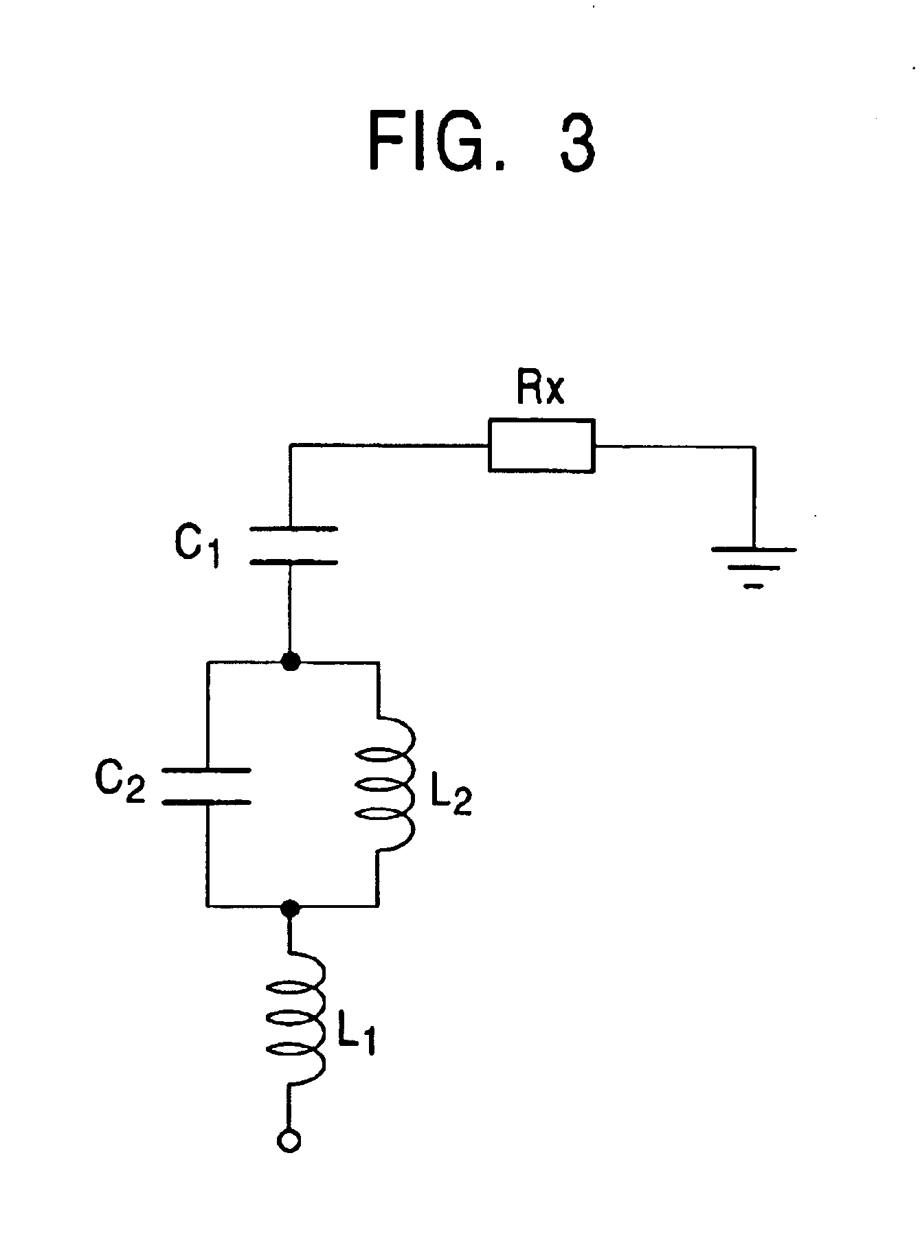
[0010]In the dual band antenna constructed as described above, if the frequency of supplied high-frequency power is relatively low, then current passes from the first meandering portion to the second meandering portion and the
capacitive coupling portion whose capacitive
reactance increases in this case can be substantially electrically shut-off in relation to the first meandering portion. This makes it possible for the entire first and second meandering portions to resonate at a longer
resonance wavelength. However, as the frequency increases, the inductive
reactance of the second meandering portion increases, while the capacitive
reactance of the
capacitive coupling portion decreases. Thus, when the frequency of supplied high-frequency power is high, it is possible to electrically connect the first meandering portion with the capacitive conductor portion through the capacitive
coupling portion so that current hardly flows to the second meandering portion. This allows only the first meandering portion to resonate at a small
resonance length. In
resonance at either high or low frequencies, the capacitive conductor portion functions as a loading
capacitor, so that the
electrical length of the radiating conductor that resonates at a predetermined frequency is decreased, permitting the height of the entire antenna to be significantly reduced.
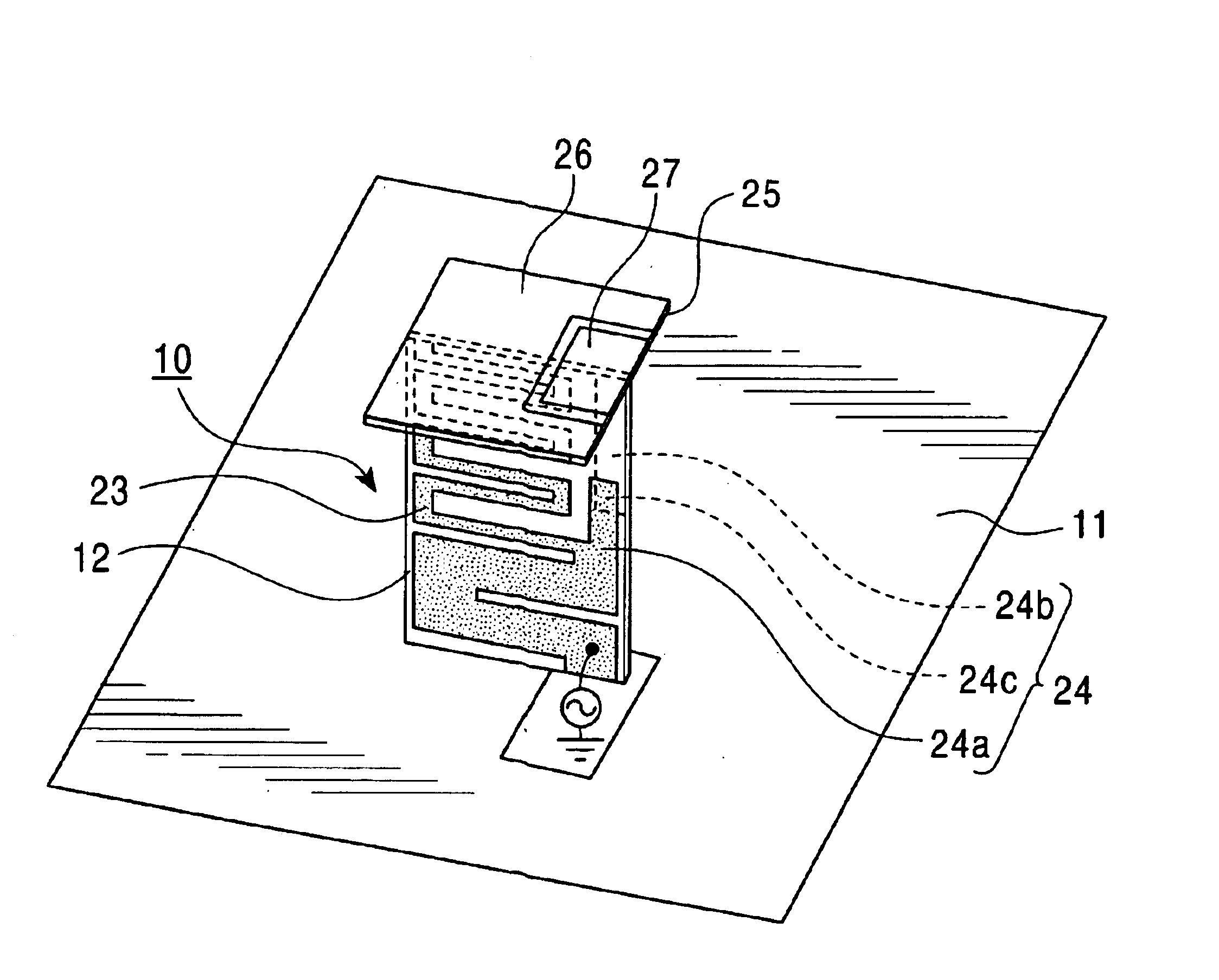
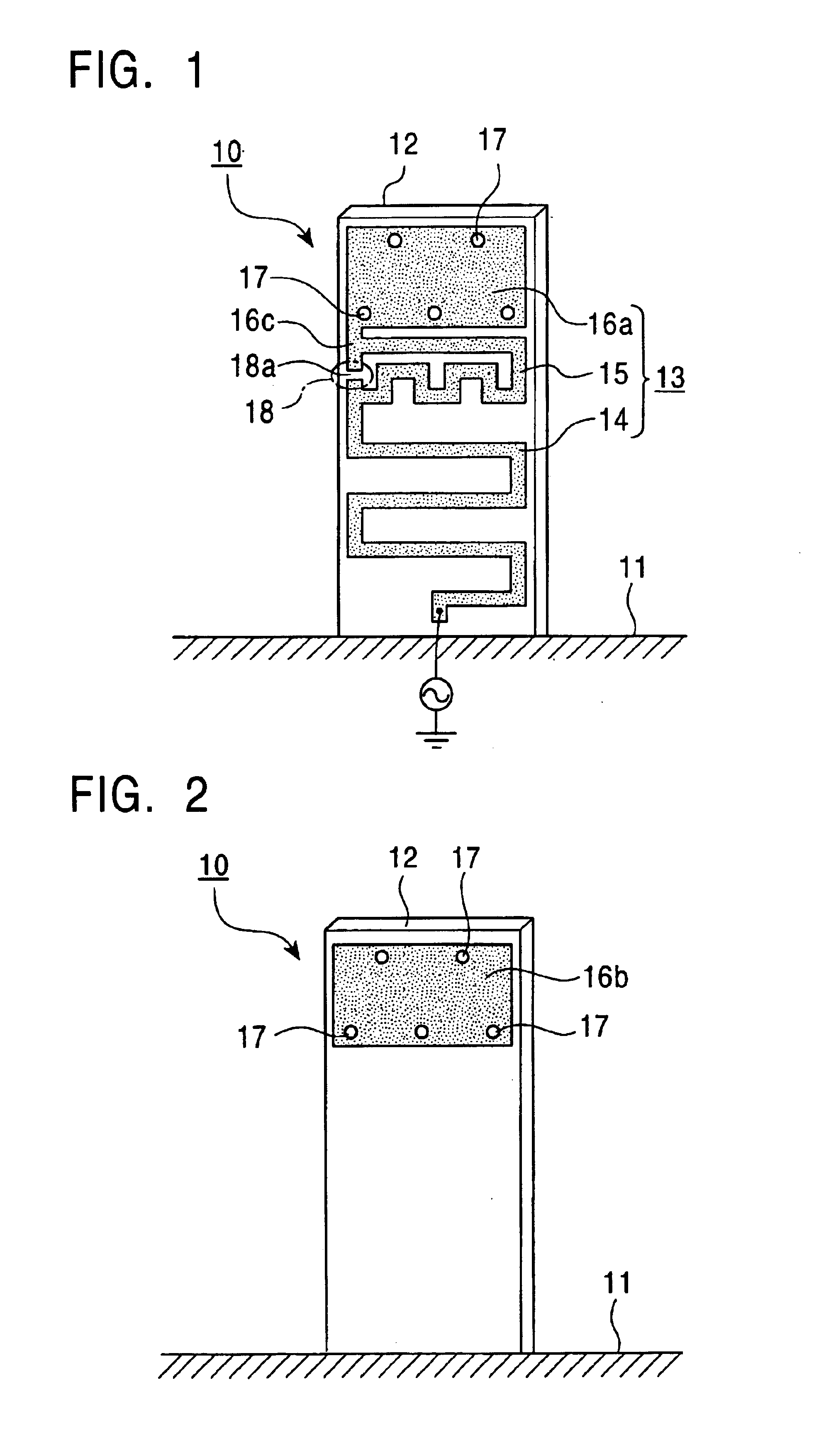
[0011]In the aforementioned construction, by providing the capacitive conductor portion on opposing surfaces of the inductive substrate and connecting the capacitive conductor portions on these surfaces via through holes, an ample area can be secured on the capacitive conductor portions without increasing the size of the entire antenna. This facilitates a reduction in the size and height of the antenna.
[0014]With this arrangement, inductive reactance of the second radiating conductor having the
meander shape increases as the frequency of supplied high-frequency power increases, making it difficult for current to pass therethrough. In contrast, the third radiating conductor makes it more difficult for current to pass therethrough as frequency decreases since the third radiating conductor has the capacitive
coupling portion. Hence, the aforementioned dual band antenna makes it possible for the second radiating conductor to resonate when high-frequency power of a relatively
low frequency is supplied, and the third radiating conductor to resonate when high-frequency power of a relatively
high frequency is supplied. Since the radiating conductors for two types of frequencies, namely, high and low frequencies, are connected in parallel, the height of the dual band antenna can be easily reduced. Moreover, the capacitive conductor functions as a loading
capacitor when at least the second radiating conductor resonates, so that the resonance frequency of the radiating conductor decreases. This leads to a shortened
electrical length of the radiating conductor required for resonance in response to a predetermined frequency, allowing the height of the entire antenna to be further reduced.
[0016]Alternatively, the second
dielectric substrate may be omitted, and a
metal conductor plate installed on the
dielectric substrate may form the first capacitive conductor. In either case, connecting the upper end of the third radiating conductor as well as- the second radiating conductor to the capacitive conductor allows the
electrical length of the third radiating conductor to be reduced.
[0018]Preferably, the second radiating conductor is provided on opposing surfaces of the first
dielectric substrate, and portions of the second radiating conductor disposed on the first and second surfaces of the first
dielectric substrate and that oppose each other with the first dielectric substrate disposed therebetween form the capacitive
coupling portion. This arrangement of the dual band antenna makes it possible to easily secure a
capacitance required for the capacitive coupling portion by utilizing the dielectric substrate and to easily reduce the height of the third radiating conductor.

