Electrophoretic display with sub relief structure for high contrast ratio and improved shear and/or compression resistance

a technology of sub relief structure and high contrast ratio, applied in the direction of electrographic process, static indicating device, instruments, etc., can solve the problems of poor scratch resistance, difficulties encountered, and own problems

Inactive Publication Date: 2005-09-20
E INK CALIFORNIA
View PDF113 Cites 57 Cited by
  • Summary
  • Abstract
  • Description
  • Claims
  • Application Information

AI Technical Summary

Problems solved by technology

However, each of these has its own problems as noted below.
However, difficulties are encountered in many aspects including the formation of the partitions, the process of filling the display with the fluid, enclosing the fluid in the display and keeping the suspensions of different colors separated from each other.
The large microcapsule size results in a poor scratch resistance and a slow response time for a given voltage because a large gap between the two opposite electrodes is required for large capsules.
Also, the hydrophilic shell of microcapsules prepared in an aqueous solution typically results in sensitivity to high moisture and temperature conditions.
If the microcapsules are embedded in a large quantity of a polymer matrix to obviate these shortcomings, the use of the matrix results in an even slower response time and / or a lower contrast ratio.
However, the microencapsulation process in an aqueous solution imposes a limitation on the type of charge controlling agents that can be used.
Other drawbacks associated with the microcapsule system include poor resolution and poor addressability for color applications.
The display fluid within a conventional display prepared by the edge sealing adhesive method will leak out completely if the display is cut in any way, or if a hole is drilled through the display.
The damaged display will be no longer functional.
Without the microcup structure, it will be very difficult to prevent the fluids in adjacent areas from intermixing or being subject to cross-talk during operation.
Also, as the opening ratio increases, undesirable particle movement such as convection flow inside the cells becomes more significant and the display contrast ratio in fact decreases.
The image uniformity of the display also deteriorates if excessive undesirable movement is present.

Method used


Image

  • Electrophoretic display with sub relief structure for high contrast ratio and improved shear and/or compression resistance
  • Electrophoretic display with sub relief structure for high contrast ratio and improved shear and/or compression resistance
  • Electrophoretic display with sub relief structure for high contrast ratio and improved shear and/or compression resistance

Examples


Embodiment Construction

Definitions

[0025]Unless defined otherwise in this specification, all technical terms are used herein according to their conventional definitions as they are commonly used and understood by those of ordinary skill in the art.

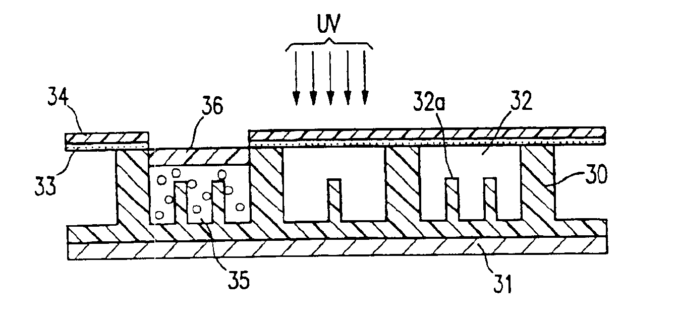
[0026]The term “microcup” refers to the cup-like indentations created by microembossing or imagewise exposure.

[0027]The term “cell”, in the context of the present invention, is intended to mean the single unit formed from a sealed microcup. The cells are filled with charged pigment particles dispersed in a solvent or solvent mixture.

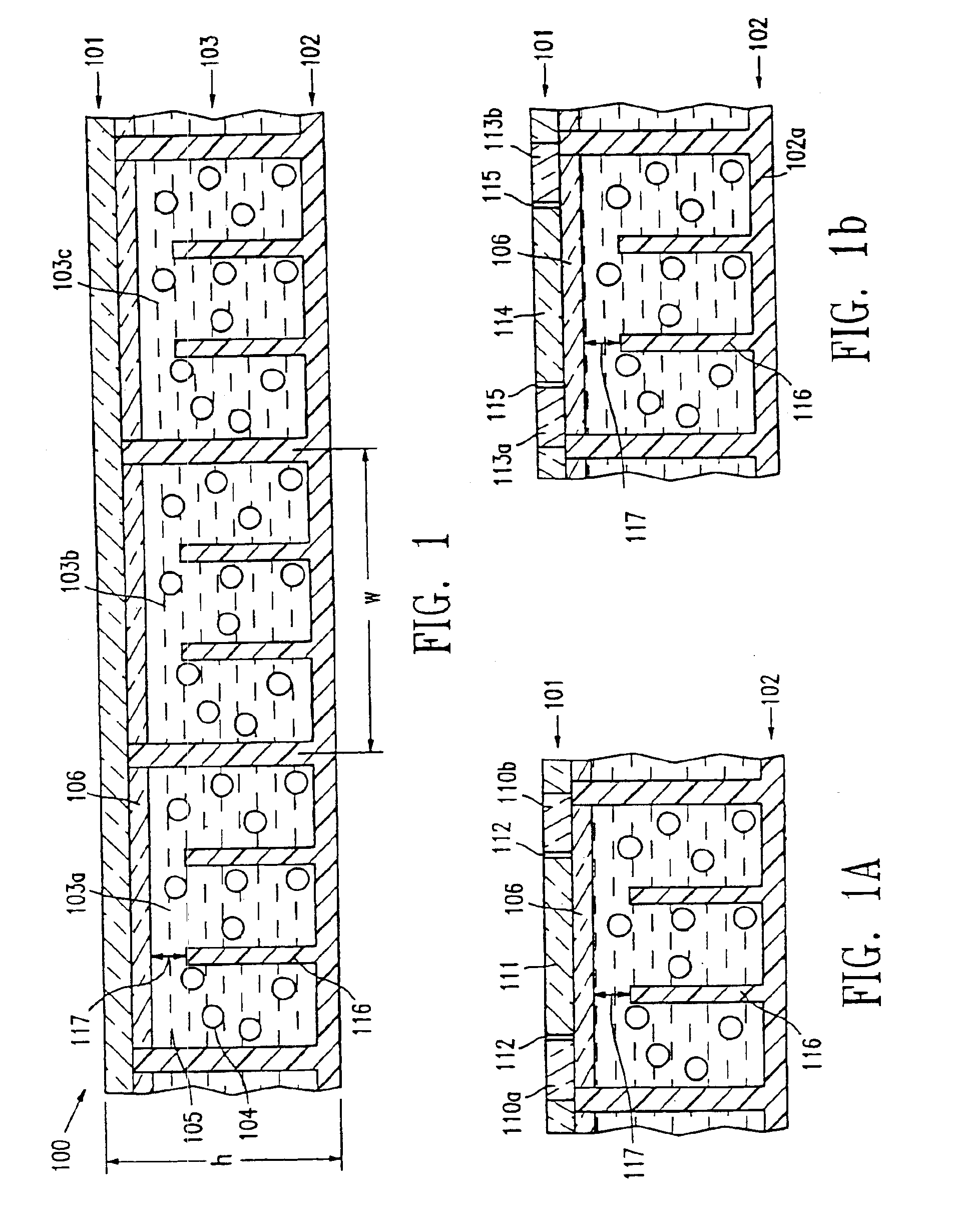
[0028]The term “well-defined”, when describing the microcups or cells, is intended to indicate that the microcup or cell has a definite shape, size and aspect ratio which are pre-determined according to the specific parameters of the manufacturing process.

[0029]The term “aspect ratio” is a commonly known term in the art of electrophoretic displays. In this application, it refers to the depth to width or depth to length ratio of the mi...


PUM

PropertyMeasurementUnit
widthaaaaaaaaaa
widthaaaaaaaaaa
widthaaaaaaaaaa

Abstract

This invention relates to an electrophoretic display comprising isolated cells of well-defined shape, size and aspect ratio which cells have internal sub relief structures and are filled with charged pigment particles dispersed in a dielectric solvent. The display shows an improved contrast ratio and resistance against shear and compression pressures. The display may have the traditional up / down switching mode, an in-plane switching mode or a dual switching mode.

Description

[0001]This application is a continuation-in-part of U.S. application Ser. No. 10 / 229,530, filed Aug. 27, 2002 now U.S. Pat. No. 6,795,229, which claims the benefit of Provisional Application 60 / 315,647, filed Aug. 28, 2001. This application is also a continuation-in-part of U.S. application Ser. No. 09 / 518,488, filed Mar. 3, 2000. The contents of all of the above-identified applications are incorporated herein by reference in their entirety.BACKGROUND OF THE INVENTION[0002]a) Field of the Invention[0003]This invention relates to an improved electrophoretic display comprising isolated cells of well-defined shape, size and aspect ratio, and the cells have internal sub relief structures and are filled with charged particles dispersed in a dielectric solvent.[0004]The display may have the traditional up / down switching mode, the in-plane switching mode or the dual switching mode.[0005]b) Description of Related Art[0006]The electrophoretic display (EPD) is a non-emissive device based on t...

Claims


Application Information

Patent Timeline
Patent Type & Authority Patents(United States)
IPC IPC(8): G02F1/01G02F1/167G02F1/13G02F1/1343G02F1/1679
CPCG02F1/167G02F1/134363G02F1/1679
Inventor LIANG, RONG-CHANGHOSSEINI, ABBASCHUANG, HSIAO-KEN
Owner E INK CALIFORNIA
Why Eureka
Try Eureka