Optoelectronic coupler

a technology of optoelectronic couplers and couplers, which is applied in the field of optoelectronic couplers, can solve the problems of affecting the performance of the coupler, the coupler is not easy to meet, and the interference is easy to be affected, and achieves the effects of low price, simple design and easy installation

Inactive Publication Date: 2005-09-20
KROHNE MESSTECHNICK GMBH & CO KG
View PDF5 Cites 15 Cited by
  • Summary
  • Abstract
  • Description
  • Claims
  • Application Information

AI Technical Summary

Benefits of technology

[0011]It is therefore an objective of this invention to introduce an optoelectronic coupler that is low-priced, simple in design and easy to install while still meeting the explosion protection requirements.
[0018]The spectral range in which the transmitting diode and the receiving diode operate may, in essence, be arbitrarily selected for as long as the spectral wavelength of the transmitting diode and that of the receiving diode are matched and the light guide functions effectively in that particular wavelength range by displaying total reflection and being sufficiently transmissive. In a preferred implementation of the invention, however, the transmitting diode and the receiving diode operate in the infrared wavelength range, since that will largely eliminate interference by parasitic ambient light. In a preferred, enhanced embodiment of the invention, the exclusion of any such interference is further supported by equipping the receiving diode with a filter that screens out light in the visible wavelength range.
[0019]It follows that the optoelectronic coupler according to the invention can be produced by simple means, i.e. with conventional photodiodes, while the light guide on its part is easy to make, consisting for instance of a plastic element with a simple physical shape. These components can be mounted on a conventional circuit board, allowing the optoelectronic coupler of this invention to be produced in its entirety as part of the circuit board assembly and preferably in a surface-mounting process.

Problems solved by technology

For measuring purposes, however, such relationship with “safe ground” is susceptible to interference due to ground return loops while also being error-prone because the connection to “safe ground” must generally be provided by the user of the measuring instrument concerned when that is put in operation.
Yet optoelectronic couplers that meet the aforementioned requirements are relatively expensive, they are predominantly in the form of hard-wired components that involve complex installation, they tend to be bulky because of the necessary spacings referred to above and the additional protective provisions, and given the minimum of 1 mm insulating space, their optical coupling is poor.
This is why optoelectronic couplers of this type most often fail to achieve rapid data transmission.

Method used


Image

  • Optoelectronic coupler
  • Optoelectronic coupler

Examples


Embodiment Construction

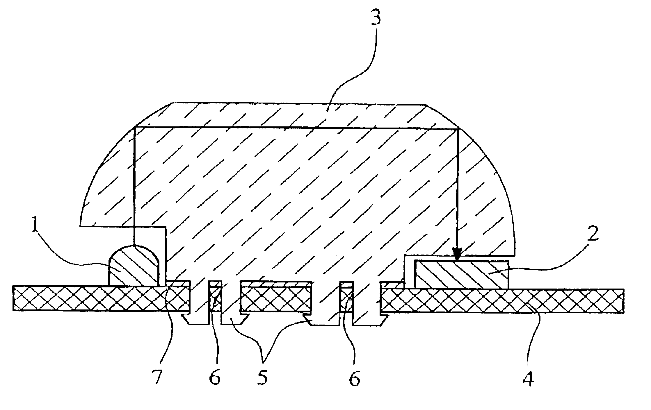
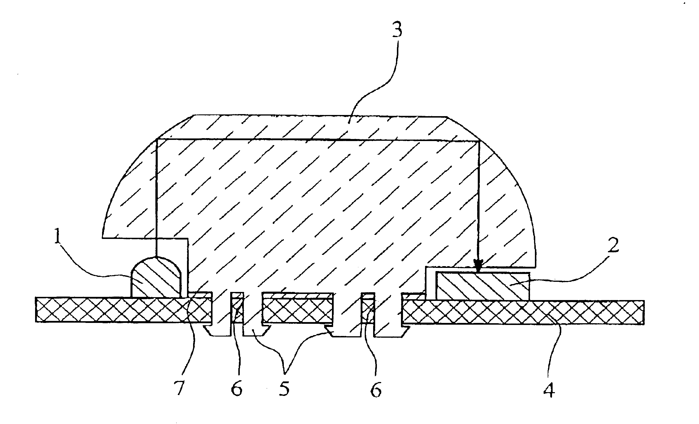
[0022]The optoelectronic coupler illustrated in the drawing FIGURE, representing a preferred embodiment of the invention, encompasses two photodiodes 1, 2, these being a transmitting diode 1 and a receiving diode 2. Positioned between the transmitting diode 1 and the receiving diode 2 is a light guide 3 that serves to guide the light emitted by the transmitting diode 1 to the receiving diode 2. The light guide 3, being transmissive to the infrared light with which the photodiodes 1, 2 operate, is a synthetic plastic element consisting of polycarbonate, e.g. a PCV 2302 material.

[0023]As is evident from the drawing, the light guide 3 has a simple geometric i.e. physical shape, enabling it to be mounted on a circuit board 4 between the two photodiodes 1, 2 and, given the positioning of the transmitting diode 1 relative to the receiving diode 2, to guide the infrared light emitted by the transmitting diode 1 to the receiving diode 2. To that effect, two mutually opposite flanks of the l...


PUM


Abstract

An optoelectronic coupler includes two photodiodes and an optic light guide, where one of the two photodiodes serves as the transmitting diode and the other as the receiving diode and the light guide serves to guide the light emitted by the transmitting diode to the receiving diode. The transmitting diode and the receiving diode are mounted on a circuit board at a distance from each other and the light guide is constituted of a plastic or glass element mounted on the same circuit board. This arrangement provides for a simple optoelectronic coupler design that permits safe operation even from the perspective of explosion protection.

Description

BACKGROUND OF THE INVENTION[0001]1. Field of the Invention[0002]This invention relates to an optoelectronic coupler with two photodiodes and an optic light guide, with one of the two photodiodes serving as the transmitting diode and the other as the receiving diode, while the light guide carries the light emitted by the transmitting diode to the receiving diode.[0003]Optoelectronic couplers as described above are frequently used for digital data transmission, especially in cases where, as explained below, explosion-protection regulations require the electroconductive separation of any two electrical circuits.[0004]In various fields of technology, as for instance in flow-rate and fill-level measurements, it is often necessary to protect the equipment employed against explosion hazards. To obtain such explosion protection, functional areas requiring different treatment must be kept separate from one another. Such separation is imperative especially for measuring systems that receive t...

Claims


Application Information

Patent Timeline
Patent Type & Authority Patents(United States)
IPC IPC(8): G02B6/12G02B6/122G02B6/42H01L31/12H01L31/0203H01L31/0232H01L31/167H01L31/173H01L31/16
CPCH01L31/0232H01L31/173H01L31/02325
Inventor FLORIN, WILHELM
Owner KROHNE MESSTECHNICK GMBH & CO KG
Why Eureka
Try Eureka