Low noise mixer circuit with improved gain

a low-noise, gain-enhancing technology, applied in the direction of oscillation generators, amplifiers with semiconductor devices/discharge tubes, transmission, etc., can solve the problems of affecting the quality of the signal, the signal input to the receiver may already be heavily distorted, and the transmission signal may be distorted

Inactive Publication Date: 2005-09-20
QORVO US INC
View PDF4 Cites 71 Cited by
  • Summary
  • Abstract
  • Description
  • Claims
  • Application Information

AI Technical Summary

Benefits of technology

[0011]According to one embodiment, the bias circuit comprises a transistor having a control input and a first and second output, wherein the control input is coupled to a bias voltage, the first output is coupled to a second reference voltage, and the second output is coupled to the common node.
[0012]According to one embodiment, the differential stage comprises a first transistor having a control input and first and second outputs. The control input of the first transistor is coupled to receive a first compo...

Problems solved by technology

However, contemporary mixer circuits such as the one illustrated in FIG. 1 are often required to perform signal processing in environments that are very sensitive to the introduction of noise.
Additionally, transmitted signals may be distorted by noise in the transmission signal path, and therefore can be more difficult to receive at the other end of the transmission medium....

Method used


Image

  • Low noise mixer circuit with improved gain
  • Low noise mixer circuit with improved gain
  • Low noise mixer circuit with improved gain

Examples


Embodiment Construction

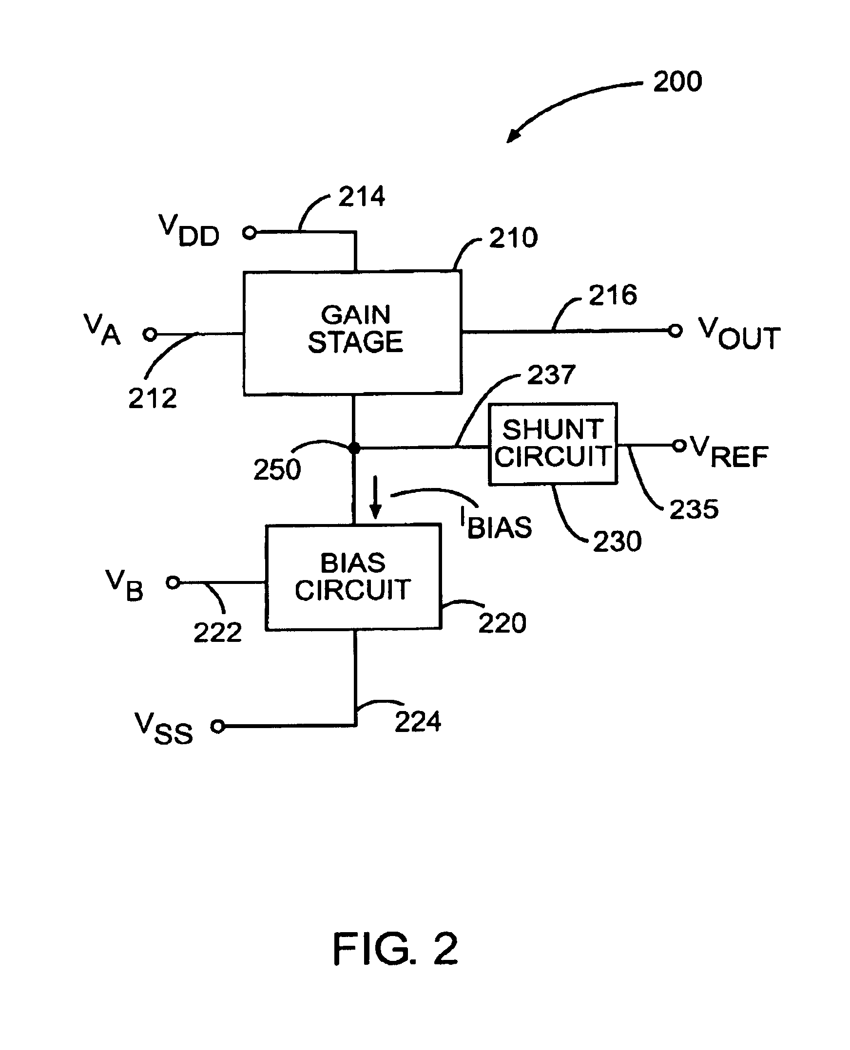
[0025]FIG. 2 illustrates a low noise mixer circuit 200 with enhanced gain according to one embodiment of the present invention. Mixer circuit 200 of FIG. 2 includes a gain stage 210, a bias circuit 220 and a shunt circuit 230. Gain stage 210 receives an input signal VA on input node 212 and produces an output signal Vout on output node 216. Additionally, gain stage 210 is powered by supply voltage Vdd received on supply terminal 214, which generates internal gain stage bias currents (not shown). The bias currents are used to set the gain of the internal devices of the gain stage and may, in turn, be coupled to common node 250.

[0026]Bias circuit 220 is coupled to common node 250 and to a second supply voltage VSS. Bias circuit 220 also receives an input signal VB on input line 222 to produce a bias current Ibias. Bias current Ibias is then coupled to common node 250 which is coupled to gain stage 210. Input signal VB may include both AC and DC frequency components. For example, the i...


PUM


Abstract

A mixer circuit of the present invention includes a gain stage configured to receive a first signal and a modulated bias current, and in accordance therewith, produce an output signal, the gain stage generating a first current and receiving the modulated bias current from a bias circuit on a common node. The bias circuit includes an input configured to receive a second signal, and in accordance therewith, generate the modulated bias current. The mixer circuit also includes a current shunt circuit for generating a second current. The first current, the second current, and the modulated bias current are coupled to the common node. In one embodiment, the first signal is approximately a square wave, and the frequency of the first signal is one-third the frequency of the second signal.

Description

CROSS-REFERENCE TO RELATED APPLICATION[0001]The present application claims priority from U.S. Non-Provisional patent application Ser. No. 09 / 691,297, filed Oct. 17, 2000, entitled “MIXER NOISE REDUCTION TECHNIQUE,” the entire disclosure of which is incorporated herein by reference.BACKGROUND OF THE INVENTION[0002]The present invention relates to mixer circuits and, more particularly, to a mixer circuit with low noise and improved gain.[0003]Mixer circuits, also known as modulator circuits, find many applications in electronic systems. For example, mixer circuits are widely used in wireless communication devices such as pagers and cellular phones to receive or transmit a modulated Radio Frequency (RF) signal. The function of a mixer circuit is to combine signals of two different frequencies in such a way as to produce energy at other frequencies. This function is typically achieved by designing a circuit that receives two input signals and produces an output that is product of the tw...

Claims


Application Information

Patent Timeline
IPC IPC(8): H03D7/14
CPCH03D7/1441H03D7/1433H03D2200/0025H03D2200/0033H03D2200/0043H03D2200/0084
Inventor RAZAVI, BEHZADZHANG, PENGFEI
Owner QORVO US INC
Why Eureka
Try Eureka