Radio base station device and radio communication method

Inactive Publication Date: 2005-09-20
MITSUBISHI ELECTRIC CORP
View PDF17 Cites 10 Cited by
  • Summary
  • Abstract
  • Description
  • Claims
  • Application Information

AI Technical Summary

Benefits of technology

[0007]An object of the present invention is to provide a base transceiver station and a radio communication method capable of efficiently and properly modulating a baseband signal with a desired carrier frequency in a simple process.
[0011]Accordingly, the baseband signal processor outputs the frequency notification signal as well as the baseband signal to the radio transmitter and receiver so that the radio transmitter and receiver is capable of instantaneously identifying the carrier frequency to be used for modulation of the arriving baseband signal so that the radio transmission signal is produced efficiently and properly.
[0013]Accordingly, since the frequency notification signal is output via the signal line for transmission of the synchronization signal, it is not necessary to provide a separate signal line for frequency notification so that the construction of the station is simplified.
[0015]Accordingly, the parity signal is output via the signal line for transmission of the synchronization signal in addition to the frequency notification signal so that it is not necessary to provide a separate signal line for the parity signal and the construction of the station is simplified.
[0021]Accordingly, the radio transmission signal is generated efficiently and properly by outputting the baseband signal and the frequency notification signal. Since the carrier frequency is assigned to the baseband signal based on the information obtained in the call process, it is ensured that the carrier frequency is assigned properly.

Problems solved by technology

In such a base transceiver station of a CDMA system, complex processes including multiplexing of multiple-channel signals and multiplexing of a variety of signals including a voice signal and a data signal are necessary.

Method used


Image

  • Radio base station device and radio communication method
  • Radio base station device and radio communication method
  • Radio base station device and radio communication method

Examples


Embodiment Construction

[0027]Hereinafter, various embodiments of the present invention will be described with reference to the drawings.

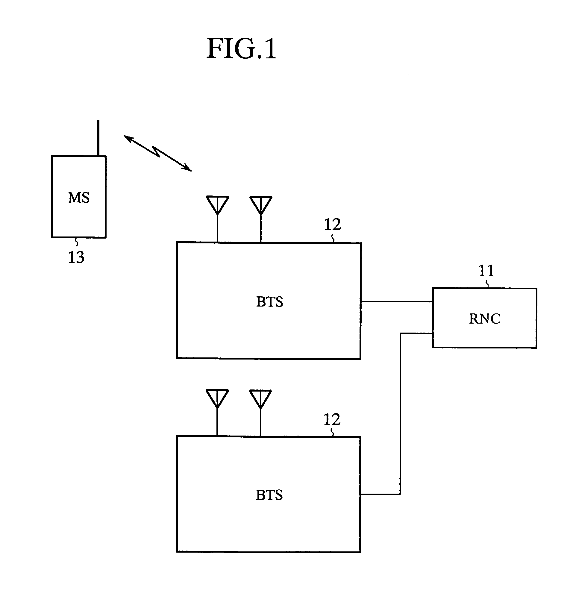
[0028]FIG. 1 is a block diagram showing an electrical construction of a radio communication system according to an embodiment of the present invention. A radio network controller (RNC) 11 is connected to a plurality of base transceiver stations (BTS) 12 so as to control the base transceiver stations 12. The base transceiver station 12 communicates with a mobile station 13 using a radio signal and communicates with the radio network controller 11 over a wire transmission channel.

[0029]With this construction, a signal from the mobile station 13 is multiplexed by the base transceiver station 12 accommodating the mobile station 13. Signals from a plurality of base transceiver stations 12 are in turn multiplexed by the radio network controller 11 so that the signal from the mobile station 13 is transmitted to another radio terminal or a stationary terminal. It is thus ensured ...


PUM


Abstract

A base transceiver station includes a baseband signal processor outputting a frequency notification signal indicating a carrier frequency for modulating a baseband signal, in combination with a baseband signal and a radio transmitter and receiver modulating the baseband signal from the baseband signal processor with the carrier frequency designated by the frequency notification signal so as to produce a radio transmission signal. By allowing the baseband signal processor to output the baseband signal and the frequency notification signal to the radio transmitter and receiver, the radio transmitter and receiver is immediately informed of the carrier frequency for modulation of the arriving baseband signal so that the radio transmitter and receiver is capable of generating a radio transmission signal efficiently and properly.

Description

TECHNICAL FIELD[0001]The present invention relates to a base transceiver station and a radio communication method of a multi-carrier type in which a baseband signal is modulated with a carrier frequency for radio transmission.BACKGROUND ART[0002]FIG. 2 shows an example of a base transceiver station of a code division multiple access (CDMA) type. The base transceiver station comprises antennas 21 and 22, a radio transmitter and receiver (TRX) 24, a baseband signal processor (BB) 25 and a call processing controller 26.[0003]In this base transceiver station, a signal is received via the antennas 21 and 22. The received signal is converted into a baseband signal by the radio transmitter and receiver 24. The baseband signal processor 25 subjects the baseband signal to spectrum despreading, error correction and the like before transmitting it to a wire network. A signal received from the wire network is subject to spectrum spreading by the baseband signal processor 25. The radio transmitt...

Claims


Application Information

Patent Timeline
IPC IPC(8): H04L5/02H04Q7/30H04W88/14H04J13/00H04L27/26H04W88/08
CPCH04L5/026H04W88/08
Inventor ITOMITSU, FUJIOKOMAWAKI, KOUICHI
Owner MITSUBISHI ELECTRIC CORP
Why Eureka
Try Eureka