Cover plate for optical disk drive

a technology of optical disk drive and cover plate, which is applied in the direction of casing/cabinet/drawer details, instruments, casings/cabinets/drawers, etc., can solve the problems of reducing the reliability of recording/playing back data, vibration of high-speed rotating disks, and the conventional optical disk drive described above has not yet adopted a structure to reduce the vibrational effect of the disk, so as to reduce the acoustic energy density of noise, reduce noise reducing noise

Inactive Publication Date: 2005-09-20
SAMSUNG ELECTRONICS CO LTD
View PDF7 Cites 25 Cited by
  • Summary
  • Abstract
  • Description
  • Claims
  • Application Information

AI Technical Summary

Benefits of technology

[0020]The present invention also provides a cover plate for an optical disk drive, which is installed above a main frame of the optical disk drive and has a through hole in the center through which a disk clamp for clamping a disk placed on a turntable is fitted. The cover plate includes first and second projections jutting out toward the disk to predetermined heights for narrowing a gap between the cover plate and the disk, and a circular step formed between the first and second projections in the shape of an annular groove for lowering acoustic energy density of noise. The first projection, the second projection, and the abruptly expanded portion are formed at portions of the cover plate opposite surfaces ...

Problems solved by technology

In an optical disk drive constructed in this way, high-speed rotating disks will usually undergo vibration.
The vibration of a disk is known to be mainly-caused by excitation due to mass unbalance and spindle motor bearing defects, mechanical resonance, excitation due to instability in a rotating disk at critical speed, and disk fluttering.
The vibration of a disk during the operation of an optical disk drive will degrade the reliability in recording/playing back data.
However, the conventional optical disk drive described above has not yet adopted a structure to reduce vibrational effects of the disk.
Furthermore, as the speed of optical disk drives increases, a disk placed therein rotates with ...

Method used


Image

  • Cover plate for optical disk drive
  • Cover plate for optical disk drive
  • Cover plate for optical disk drive

Examples


first embodiment

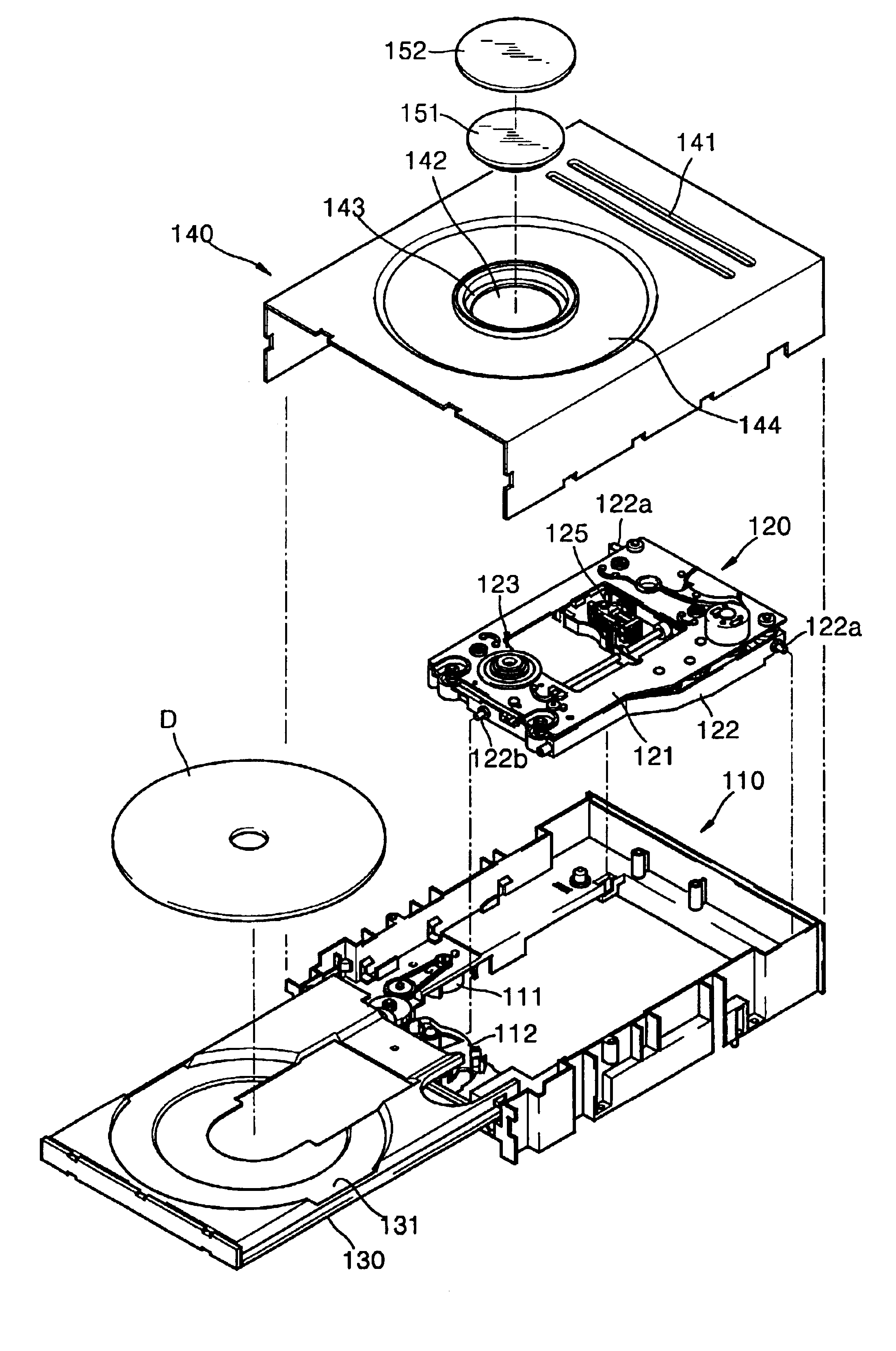
[0035]Referring to FIGS. 4 and 5, a cover plate 140 according to the present invention is installed above a main frame 110 of an optical disk drive to cover a disk D and a deck assembly 120. A tray 130 having a surface 131 on which a disk D is to be placed and transporting the disk D is coupled to a main frame 110 so that it slides into or out of the main frame 110. A deck assembly 120 has a deck base 122, and a deck plate 121 supported by the deck base 122. The deck base 122 is installed so that it can rotate with respect to the main frame 110 by means of a hinge pin 122a projecting out on its sides. The deck plate 121 consists of a turntable 123 on which the disk D transported by the tray 130 is placed, a spindle motor 124 for rotating the turntable 123, and an optical pickup 125 for recording and playing back information on the disk D. The tray 130 is driven by the loading motor 120 so that it moves into or out of the main frame 110. The deck assembly 120 moves up and down by a c...

second embodiment

[0043]As the disk D rotates at high speed, as described above, various kinds of noise are generated. Since linear velocity on the outer circumference of the disk D is at least four times higher than that on the inner circumference, air pressure on the outer circumference of the disk D is lower than that on the inner circumference. Thus, rotation of the disk D and the pressure difference create a turbulent air flow whirling from the inner circumference to the outer circumference. The noise is then transmitted along this air flow from the inner circumference of the disk D into the outer circumference. As the first gap G1 between the disk D and the first projection 244a, through which air flows, becomes significantly wider on the surface corresponding to the outer circumference of the disk D due to the circular step 246, acoustic energy density of noise escaping through the first gap G1 drastically decreases in the circular step 246. Noise in which acoustic energy density decreases in ...


PUM


Abstract

A cover plate for an optical disk drive designed to reduce disk vibrations and noise is provided. The cover plate is installed above a main frame of the optical disk drive and has a through hole in the center through which a disk clamp for clamping a disk placed on a turntable is fitted and a projection formed to oppose the disk up to a predetermined height in order to narrow a gap with the disk. Furthermore, the cover plate has a circular step formed opposite a surface corresponding to an outer circumference of the disk in the shape of an annular groove for lowering acoustic energy density of noise. The cover plate constructed in this way reduces disk vibration due to air damping effects resulting from a narrow gap between the disk and the cover plate while suppressing noise due to the presence of the abruptly expanded portion. Furthermore, the cover plate can be implemented without a separate device by making simple changes to the structure of cover plate.

Description

BACKGROUND OF THE INVENTION[0001]This application claims the priority of Korean Patent Application No. 2002-594 filed on Jan. 5, 2002 in the Korean Intellectual Property Office, the disclosure of which is incorporated herein in its entirety by reference.[0002]1. Field of the Invention[0003]The present invention relates to an optical disk drive, and more particularly, to a cover plate for an optical disk drive designed to reduce vibration and noise occurring during the rotation of a disk.[0004]2. Description of the Related Art[0005]An optical disk drive is an apparatus that reads data from and writes data onto a recording medium such as a compact disk (CD) or a digital video disk (DVD) by emitting a laser beam onto the disk. An important research area in this respect is the possibility of achieving high speed and reducing noise and vibration of optical disk drives.[0006]FIG. 1 is a schematic exploded perspective view of a conventional optical disk drive, and FIG. 2 is a vertical cros...

Claims


Application Information

Patent Timeline
IPC IPC(8): G11B33/08G11B17/028G11B33/14G11B25/04
CPCG11B17/0284G11B17/0285G11B33/08G11B33/1486G11B17/028
Inventor CHO, EUN-HYOUNGSOHN, JIN-SEUNGPARK, JUN-MIN
Owner SAMSUNG ELECTRONICS CO LTD
Why Eureka
Try Eureka