Vehicle for sweeping streets

Inactive Publication Date: 2005-09-27
SHINJEONG DEV
View PDF10 Cites 16 Cited by
  • Summary
  • Abstract
  • Description
  • Claims
  • Application Information

AI Technical Summary

Benefits of technology

[0014]Accordingly, the present invention has been made in an effort to solve the problems occurring in the related art, and an object of the present invention is to provide a vehicle for sweeping streets in which water carried i

Problems solved by technology

If the refuse is introduced into and accumulates in a sewer pipe, the sewer pipe is likely to be clogged by the refuse.
As a consequence, flow of sewage is obstructed, and, as a result of this, backflow of sewage may take place.
Also, when compared to the case of sweeping refuse on the street, a great deal of costs are incurred upon removing the refuse after introduction thereof into the sewer pipe, whereby economic loss is caused.
In the case that a sanitation engineer manually sweeps the street, a possibility of the sanitation engineer to be exposed to a traffic accident is increased.
Even if it is possible to collect using a dust separator, the fine dust particles contained in an air stream, since a conventional dust collector generally has a large size, it is difficult to practically install in practice the large-sized dust collector on the vehicle for sweeping streets.
However, a filtering effect accomplished by the filtering screen 3 is so poor that a substantial amount of fine dust particles are exhausted to the atmosphere as they are.
These fine dust particles exhausted to t

Method used


Image

  • Vehicle for sweeping streets
  • Vehicle for sweeping streets
  • Vehicle for sweeping streets

Examples


Example

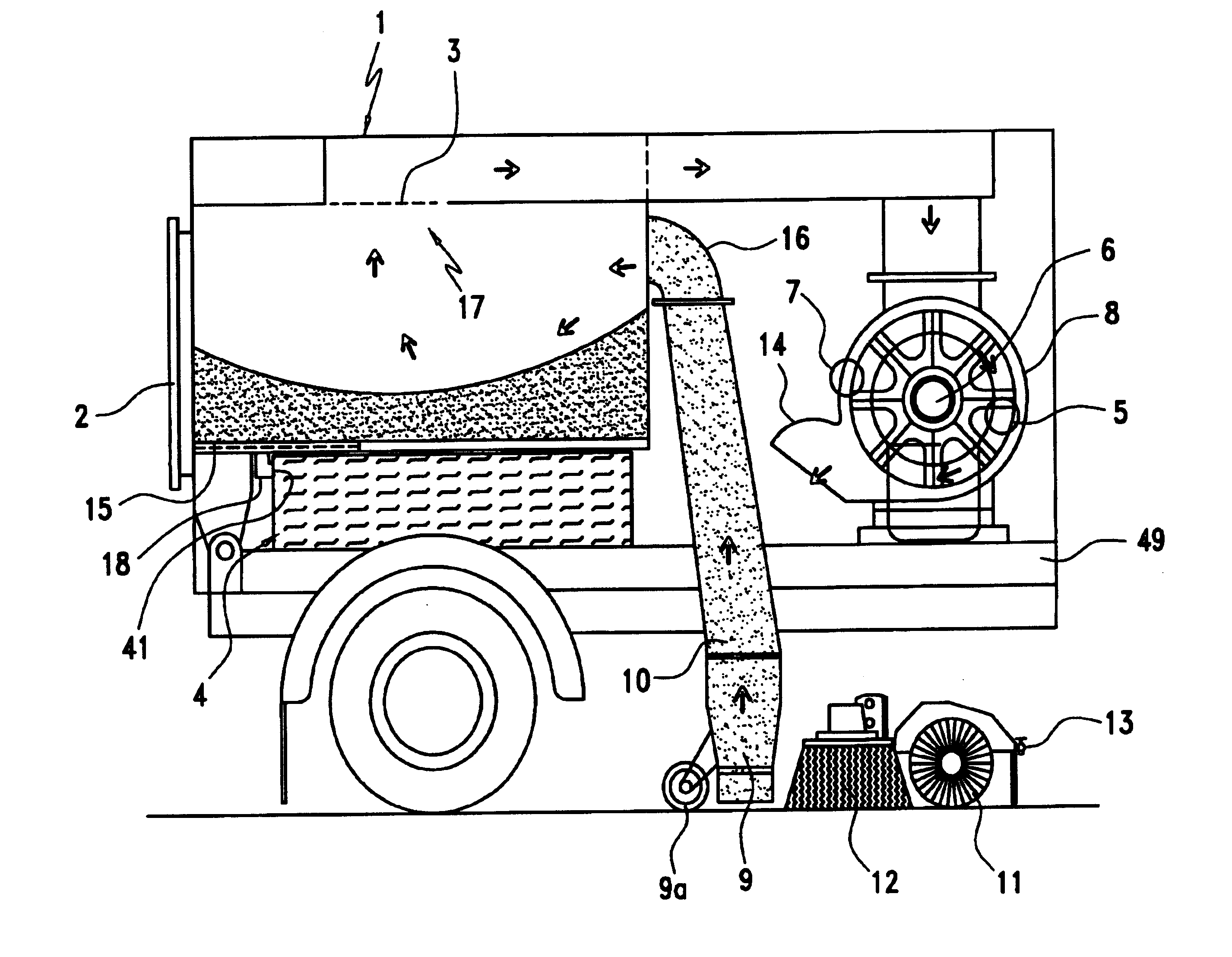
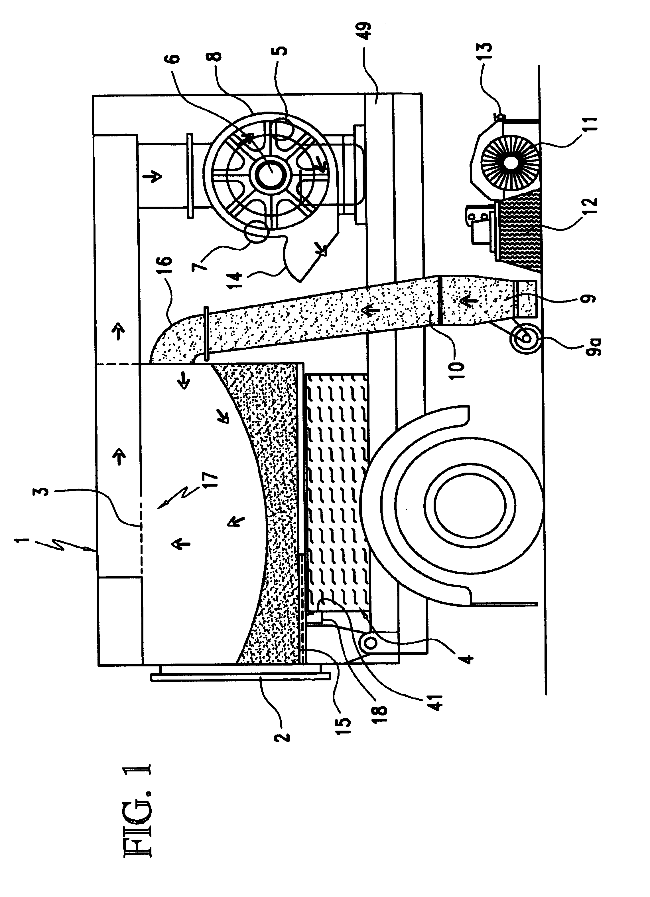
[0036]Reference will now be made in greater detail to a preferred embodiment of the invention, an example of which is illustrated in the accompanying drawings. Wherever possible, the same reference numerals will be used throughout the drawings and the description to refer to the same or like parts.

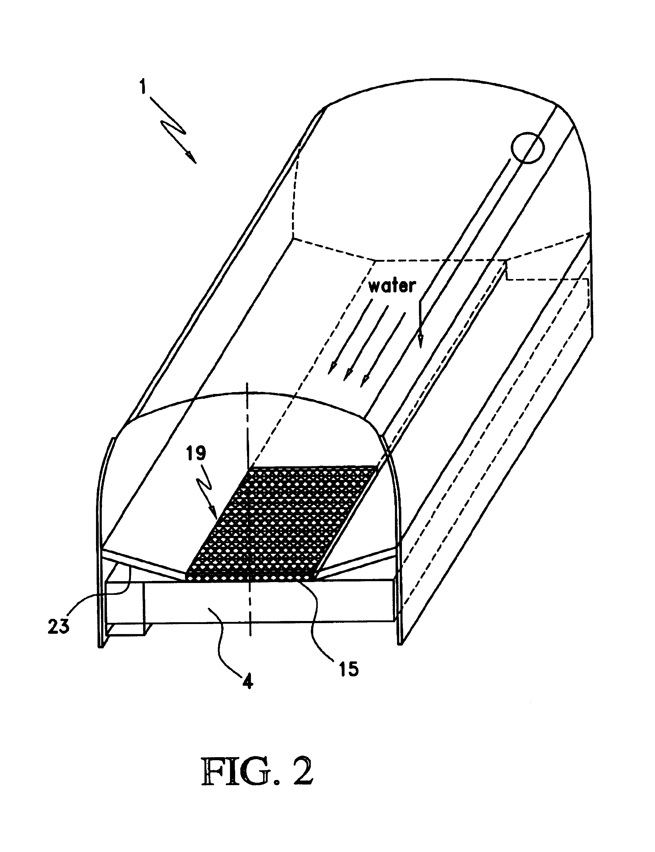
[0037]Referring to FIG. 1, there is illustrated a positional relationship between a collection hopper 1 and a water tank 4 mounted on a vehicular frame (49) in a vehicle for sweeping streets in accordance with an embodiment of the present invention. It is to be readily understood from FIG. 1 that a drain pipe 18 is arranged between a bottom wall of the collection hopper 1 and a rear wall of the water tank 4. The water tank 4 is mounted on a vehicular frame 33.

[0038]A refuse suction tube 9 is supported by a support roller 9a in a manner such that it is positioned at a predetermined separation above the street. The support roller 9a is secured to a rear surface of the refuse suction tube 9. ...


PUM


Abstract

Disclosed is a street sweeper. The street sweeper includes a water tank, a collection hopper delimiting a refuse accommodating space and having a filtering screen, water spraying nozzles connected to the water tank, brushes positioned close to the street, a refuse suction tube placed adjacent to the brushes, and a blower unit for inducing suction force in the refuse suction tube. The street sweeper is adapted for sucking and collecting refuse existing on the street through the refuse suction tube into the collection hopper while water is sprayed from the water spraying nozzles. An opening is defined through a bottom wall of the collection hopper. A water inlet hole to be communicated with the opening is defined through a wall of the water tank. A filter assembly is arranged between the opening of the collection hopper and the water inlet hole of the water tank.

Description

TECHNICAL FIELD[0001]The present invention relates to a vehicle for sweeping streets which is operated through manipulation of levers or switches by a driver riding thereon to dislodge and pick up dirt and debris from a street, expressway, parking lot, industrial complex, landing strip, stadium, etc.BACKGROUND ART[0002]Recently, with the improvement of living standards, people's concern about environmental beautification is gradually increased. In this regard, since dirt, leaves, gravel and the like (hereinafter, simply referred to as “refuse”), which are scattered on the street, defile the appearance of the street, it is necessary to frequently sweep them up.[0003]If the refuse is introduced into and accumulates in a sewer pipe, the sewer pipe is likely to be clogged by the refuse. As a consequence, flow of sewage is obstructed, and, as a result of this, backflow of sewage may take place. Also, when compared to the case of sweeping refuse on the street, a great deal of costs are in...

Claims


Application Information

Patent Timeline
IPC IPC(8): E01H1/08E01H1/00
CPCE01H1/0845
Inventor KIM, JONGSOON
Owner SHINJEONG DEV
Why Eureka
Try Eureka