Television receiver and cold-cathode tube dimmer

a technology receiver, which is applied in the direction of television system, process and machine control, etc., can solve the problems of not adopting the method of controlling the brightness of cold cathode tube, difficult to apply the third prior art to the case, and reducing the variation in the luminance of backlight. , to achieve the effect of enhancing the control accuracy of the luminance of backligh

Inactive Publication Date: 2005-09-27
FUNAI ELECTRIC CO LTD
View PDF9 Cites 14 Cited by
  • Summary
  • Abstract
  • Description
  • Claims
  • Application Information

AI Technical Summary

Benefits of technology

[0013]This invention has been accomplished in order to solve the above problems. An object of this invention is to provide a television receiver which can reduce a variation in the luminance of backlight when the luminance of the backlight of a liquid crystal panel is stabilized to a target luminance by controlling the duty ratio of lighting / driving of a cold-cathode tube, can enhance the control accuracy of the luminance of the backlight, and can prevent the upsizing of a control element for controlling the lighting / driving of the cold-cathode tube as compared with the case where the lighting / driving of the cold-cathode tube and its stopping are carried out by turning on / off the power source path.
[0014]Another object of this invention is to provide a cold-cathode tube dimmer which can reduce a variation in the luminance of a cold-cathode tube when the luminance of the cold-cathode tube is stabilized to a target luminance by controlling the duty ratio of lighting / driving of the cold-cathode tube in such a manner that the frequency characteristic of a low-pass filter to which the rectified output of the voltage across a resistor inserted in a current path to the cold-cathode tube is supplied is a characteristic of removing the frequency component of the signal for lighting / driving the cold-cathode tube and passing the frequency component of an intermittent control signal indicative of the duty ratio of the lighting / driving interval of the cold-cathode tube to its stopping interval, and a multiplied value of the ratio of an interval during which the level of an extracted signal is higher than a prescribed level to the period thereof and the level of the extracted signal for the interval during which it is higher than the prescribed level is computed as an average value of the current flowing through the cold-cathode tube so that the duty ratio of lighting / driving the cold-cathode tube is a value corresponding to the current average value thus computed.
[0015]Still another object of this invention is to provide a cold-cathode tube dimmer which can further enhance the control accuracy of luminance by enhancing the detection accuracy of the average value of the current flowing through the cold-cathode tube in such a manner that the frequency of an intermittent control signal indicative of the duty ratio of the lighting / driving interval of the cold-cathode tube to its stopping interval is set as a frequency lower than 1 / 10 of the frequency of the signal for lighting / driving the cold-cathode tube, and the filter for removing the frequency component of the signal for lighting / driving the cold-cathode tube and passing the frequency component of an intermittent control signal indicative of the duty ratio is designed as a n-type filter.

Problems solved by technology

However, the first prior art presented the following problem.
Thus, in the case where the this prior art is applied to the backlight for a television receiver equipped with a liquid crystal display, the signal is susceptible to the influence of changes in the power source voltage and temperature, thereby providing a variation in the brightness on the screen.
However, the third prior art does not adopt the method of controlling the brightness of the cold-cathode tube by changing the duty ratio of the lighting / driving signal.
However, since the configuration as a premise is different, it is difficult to apply the third prior art to the case where the brightness of the cold-cathode tube should be stabilized accurately in an apparatus for controlling the brightness by changing the duty ratio of the lighting / driving signal for driving the cold-cathode tube.
Therefore, like the third prior art, it is difficult to apply this second prior to the closed loop control in which the current flowing through the cold-cathode tube is detected and the duty ratio of the lighting / driving signal for driving the cold-cathode tube is changed according to the result of detection.
Further, the fourth prior art does not describe in detail how the output from an error voltage detecting circuit is processed in the adder unit.
Therefore, it is difficult to apply this fourth prior art to the case where the brightness of the cold-cathode tube should be stabilized accurately in a configuration for controlling the brightness in a configuration in which the current flowing through the cold-cathode tube is detected and the duty ratio of the lighting / driving signal for driving the cold-cathode tube is changed according to the result of detection.

Method used


Image

  • Television receiver and cold-cathode tube dimmer
  • Television receiver and cold-cathode tube dimmer
  • Television receiver and cold-cathode tube dimmer

Examples


Embodiment Construction

[0028]Now referring to the drawings, an explanation will be given of various embodiments of this invention.

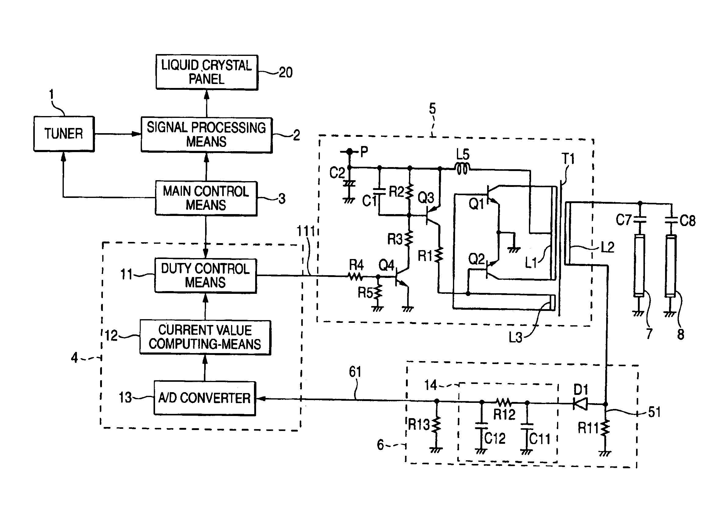
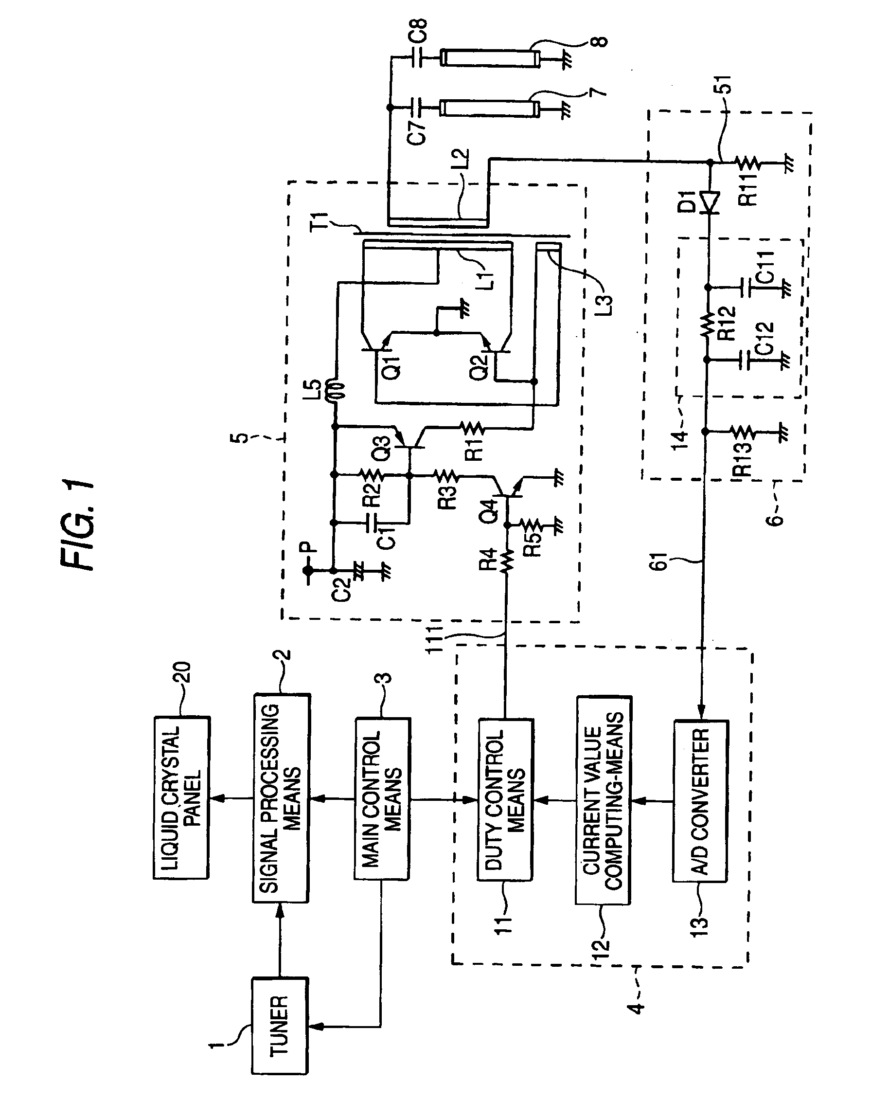
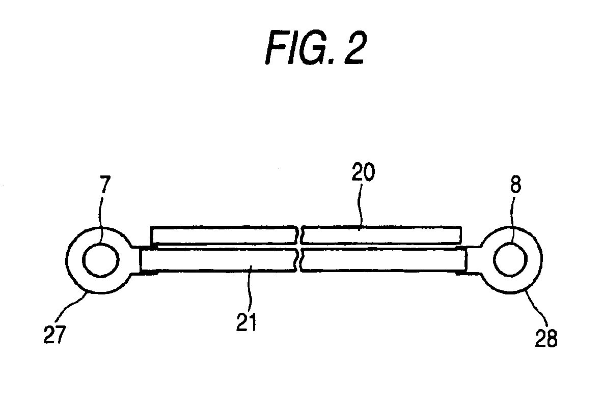
[0029]FIG. 2 is a sectional view of the structure of a backlight equipped with cold-cathode tubes of which the luminance is controlled by the cold-cathode tube dimmer according to an embodiment of this invention.

[0030]In FIG. 2, a light conducting plate 21 is made of white synthetic resin and has a rectangular flat shape in a flat view. The light conducting plate 21 is provided with slender cylindrical cold-cathode tubes 7 and 8 at both ends, respectively. The light conducting plate 21 is provided with reflecting plates 27 and 28 around the cold-cathode tubes 7 and 8, respectively. The reflecting plates 27 and 28 serve to reflect the light from the cold-cathode tubes 7 and 8 toward the conducting plate 21, respectively. On the front side (upper side in the drawing) of the light conducting plate 21, a liquid crystal panel is arranged which passes the light from the light conduct...


PUM


Abstract

In a cold-cathode dimmer, a current detector includes a LPF for removing the frequency component of a lighting / driving signal for a lighting driver from the output of a diode for rectifying the voltage across a current detecting resistor and passing the frequency component of an intermittent control signal for controlling the duty ratio of the lighting / driving signal. A luminance controller includes a current value computing section for producing, as a current average value, a multiplied result of a ratio of an interval during which the output level of the LPF is higher than a prescribed level to a period of the output of the LPF and the output level of the LPF during the interval during which it is higher than the prescribed level, and a duty controller for stabilizing a luminance of cold-cathode tubes at a target luminance in such a manner that the duty ratio of the intermittent control signal is set at a value corresponding to a difference between the current average value outputted from the current value computing section and a target value thereof.

Description

BACKGROUND OF THE INVENTION[0001]1. Field of the Invention[0002]This invention relates to a television receiver and a cold-cathode tube dimmer for controlling the brightness of a cold-cathode tube by controlling the ratio of the interval during which the lighting / driving of the cold-cathode tube is done to the interval during which the lighting / driving of the cold-cathode tube is stopped.[0003]2. Description of the Related Art[0004]In the case where the brightness of a cold-cathode tube is controlled in such a manner as to change the voltage of a lighting / driving signal for lighting the cold-cathode tube, when the voltage of the lighting / driving signal is lowered, a phenomenon occurs that the end of the side on which a minus voltage is applied becomes dark. This makes a dimmable range narrow. In order to overcome such an inconvenience, various prior arts have been proposed in which the luminance of the cold-cathode tube is controlled by changing the duty ratio of the lighting / drivin...

Claims


Application Information

Patent Timeline
Patent Type & Authority Patents(United States)
IPC IPC(8): H05B41/282H05B41/39H05B41/392H05B41/28H04N5/57
CPCH04N5/57H05B41/2821H05B41/2824H05B41/3927Y02B20/186Y02B20/00
Inventor HIGUCHI, YOSHIO
Owner FUNAI ELECTRIC CO LTD
Why Eureka
Try Eureka