
Efficient broadband switching-mode amplifier

a broadband switching-mode amplifier and amplifier technology, applied in the field of amplifiers, can solve the problems of complex microwave baluns with limited bandwidth, low power consumption, and low power consumption, and achieve the effect of improving power consumption, facilitating amplifier switching-mode operation, and presenting invention

Inactive Publication Date: 2005-09-27
RAYTHEON CO
View PDF6 Cites 21 Cited by
  • Summary
  • Abstract
  • Description
  • Claims
  • Application Information

AI Technical Summary

Benefits of technology

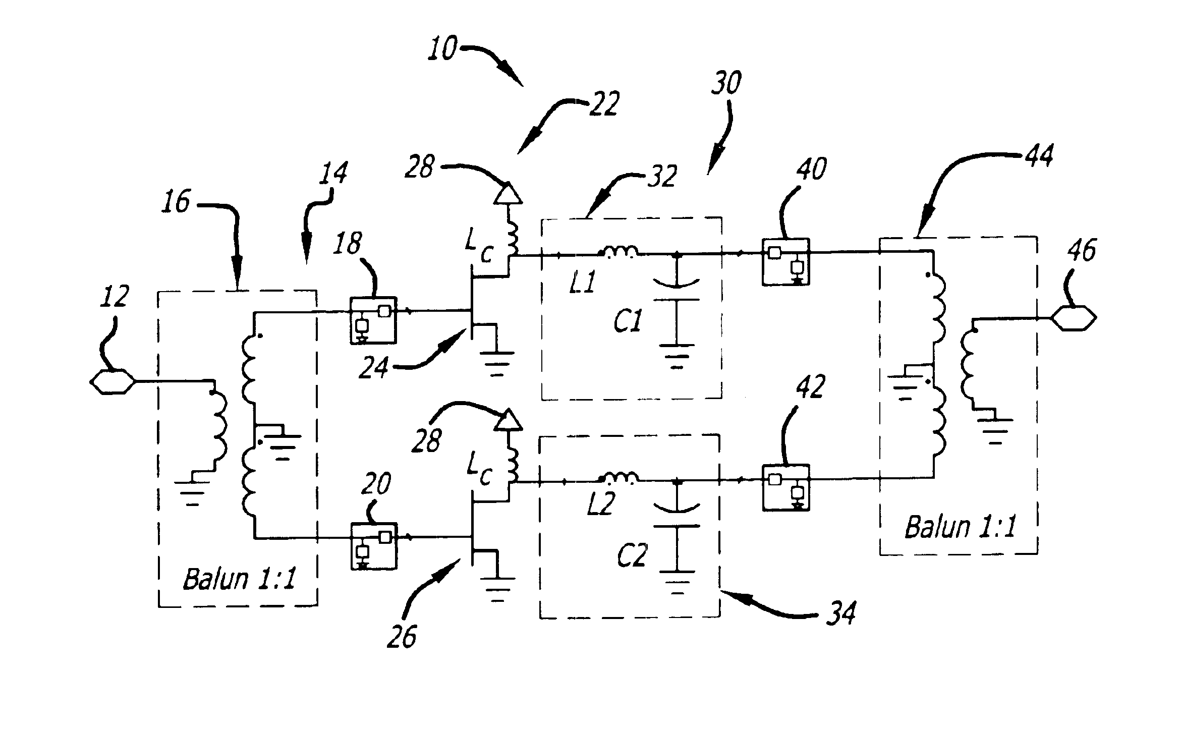
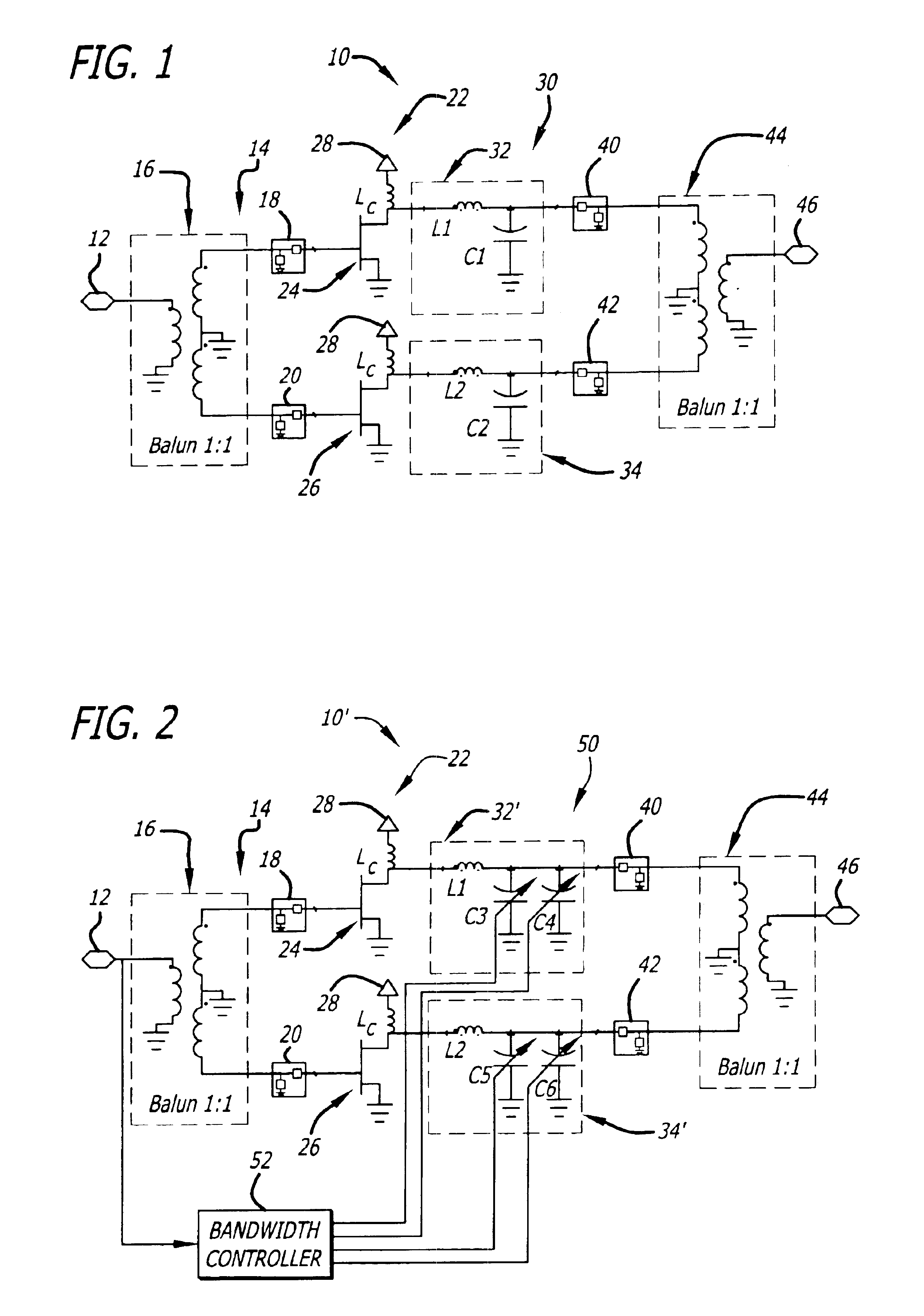
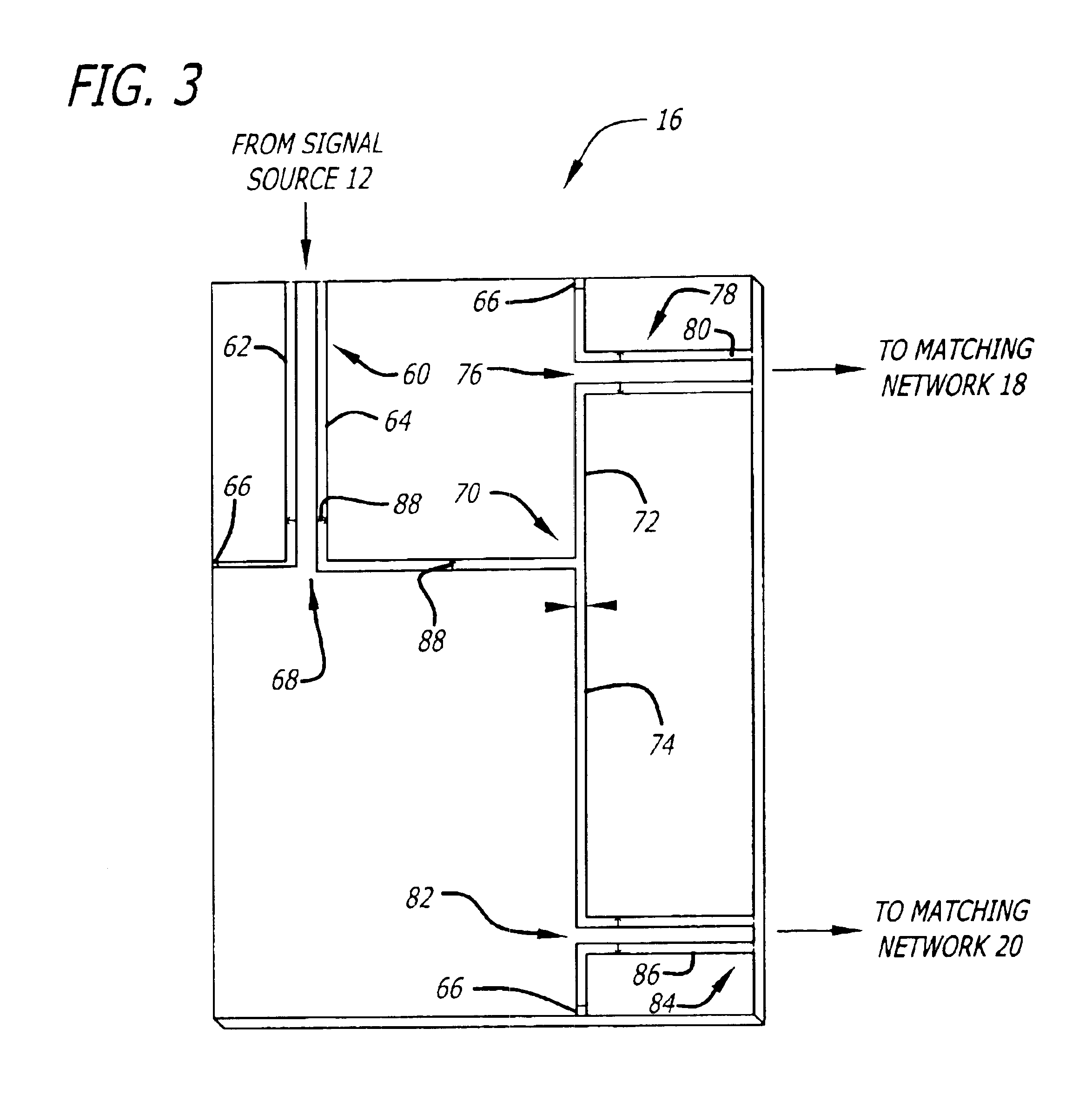
The present invention is an efficient broadband amplifier that can amplify an input signal and filter it using common mode rejection. The amplifier includes a mechanism for amplifying the input signal and a mechanism for filtering it using common mode rejection. The filtering mechanism separates the input signal into multiple intermediate signals and amplifies them using high-speed transistors. The amplified signals are then combined using a broadband output balun to produce an output signal with reduced common mode components. The amplifier also includes an output-matching network with tunable capacitors to optimize amplifier bandwidth. The unique design of the amplifier allows for ultra compact and high-performance operation.

Problems solved by technology

Internal power dissipation due to overlapping voltage and current waveforms at the amplifier's active device terminals and inefficiencies in output matching network baluns often limit PAE to below 50%, which is undesirably low for various applications, such as space-based radar.
These conventional amplifiers often employ complex microwave baluns that have limited bandwidth and high insertion loss at X-band and that are difficult to integrate with accompanying chipsets.
Attempts to improve HPA efficiency and applicability via GaAs Monolithic Microwave Integrated Circuit (MMIC) technology have produced limited results.
Currently, highly efficient microwave power amplifiers that operate at PAE's above 60% at frequencies over 2 GHz are unavailable.

Method used


Image

  • Efficient broadband switching-mode amplifier
  • Efficient broadband switching-mode amplifier
  • Efficient broadband switching-mode amplifier

Examples


Embodiment Construction

[0027]While the present invention is described herein with reference to illustrative embodiments for particular applications, it should be understood that the invention is not limited thereto. Those having ordinary skill in the art and access to the teachings provided herein will recognize additional modifications, applications, and embodiments within the scope thereof and additional fields in which the present invention would be of significant utility.

[0028]FIG. 1 is a diagram of an efficient broadband switching-mode amplifier 10 constructed in accordance with the teachings of the present invention. For clarity, various features, such as transistor doping profiles, W / L ratios, class-E driver circuits, and so on, have been omitted from the figures. However, those skilled in the art with access to the present teachings will know which features to implement and how to implement them to meet the needs of a given application.

[0029]The efficient broadband switching-mode amplifier 10 incl...


PUM


Abstract

An efficient broadband amplifier. The amplifier includes a mechanism for amplifying an input signal via a high-speed switch and providing an amplified signal in response thereto. Another mechanism filters the amplified signal via common mode rejection and provides an output signal in response thereto. In a specific embodiment, the mechanism for filtering includes a first mechanism for separating an input signal into plural intermediate signals. The mechanism for amplifying includes a second mechanism for amplifying the plural intermediate signals via one or more high-speed switches and providing plural amplified signals in response thereto. The mechanism for filtering further includes a third mechanism for employing common mode rejection to filter the plural amplified signals, yielding a single output signal in response thereto.

Description

BACKGROUND OF THE INVENTION[0001]1. Field of Invention[0002]This invention relates to amplifiers. Specifically, the present invention relates to broadband switching-mode amplifiers.[0003]2. Description of the Related Art[0004]High Power Amplifiers (HPA's) are employed in various demanding applications including telecommunications, avionics systems, digital radio transmitters, military targeting and tracking, and transceiver modules for phased array radar systems. Such applications require efficient, lightweight, compact, cost-effective, high power amplifiers. Cost, size, weight, and efficiency considerations are particularly important in space-based transceiver applications, such as space-based phased array radar systems, where any extra size, weight, or HPA inefficiencies can dramatically increase overall mission cost.[0005]Conventional amplifiers are often either Class A, B, A-B, or C amplifiers that operate at a Power Added Efficiencies (PAE's) of less than 50% at X-band, which i...

Claims


Application Information

Patent Timeline
Patent Type & Authority Patents(United States)
IPC IPC(8): H03F3/217H03F3/20H03F1/56H03F3/191H03F3/26
CPCH03F1/565H03F3/191H03F3/2171H03F3/265H03F2200/331
Inventor TAYRANI, REZAMEYERS, CLIFFORD W.
Owner RAYTHEON CO
Learn More