Electrical circuit interrupter

a circuit interrupter and circuit board technology, applied in the direction of emergency protective arrangements for limiting excess voltage/current, emergency protective arrangements for automatic disconnection, electrical equipment, etc., can solve the problems of poor reliability, high manufacturing cost, complicated structure of conventional gfci devices, etc., to achieve simple manufacturing, high reliability, and added rigidity to the circuit board structure

Inactive Publication Date: 2005-09-27
EATON INTELLIGENT POWER LTD
View PDF27 Cites 27 Cited by
  • Summary
  • Abstract
  • Description
  • Claims
  • Application Information

AI Technical Summary

Benefits of technology

[0008]An object of the invention is to provide an fault / error detection device that is economic to manufacture, requires as few parts as possible and operates at a high level of reliability. Another object of the present invention is to provide a GFCI device that requires no more than one splice and no more than one pair of contacts along each current path located in the GFCI device. Yet another object of the invention is to provide a GFCI device that includes a cantilevered contact which can be opened to prevent current flow there through by an activation device that moves in a linear motion. Another object of the invention is to provide a GFCI device that includes a transformer boat and a solenoid bobbin that snap onto the circuit board and are located adjacent each other to provide added rigidity to the circuit board structure. A further object of the invention is to provide a GFCI device that has a linearly actuatable test switch that is simple to manufacture and operates reliably. Specifically, it is an object of the invention to provide a GFCI device in which the test switch includes a cantilevered integral extension from the output contact bar such that it can be bent by a one piece linearly actuated test switch to make contact with a test circuit and cause the GFCI device to trip. Yet another object of the invention is to provide a GFCI device with a housing that is easy to install and includes improved ergonomic features. Another object of the invention is to provide a GFCI device that is simple to manufacture and includes as few parts as possible while also providing the structural stability necessary for the device to be tested on a regular basis. A further object of the invention is to reduce the heat that occurs along the current path by minimizing the number of electrical splices (e.g., solders and welds) along the current path. Another object of the invention is to eliminate the use of separate bus bars or wires attached between the input line and a conductor that runs through the transformer. A still further object of the invention is to provide a separator that is integral with the middle housing to separate the conductors running through the transformer, thereby eliminating the need for a cover over the transformer. Another object of the invention is to provide a GFCI device that will not burn out after it is tripped by including a “dead” mode or “desensitized” mode that turns off the ground fault detection device once it is tripped until it is reset. Yet another object of the invention is to provide a GFCI device that includes a test light indicator that will indicate when the GFCI device has been tripped and whether the GFCI device is wired correctly.

Problems solved by technology

Conventional GFCI devices are often complicated structures that require sophisticated manufacturing processes to ensure that they work properly and safely.
Several other drawbacks exist in the conventional GFCI devices, including high manufacturing cost, poor reliability, poor endurance, potential safety concerns due to excessive heat generation and / or poor reliability, and general aesthetic and ergonomic drawbacks.

Method used


Image

  • Electrical circuit interrupter
  • Electrical circuit interrupter
  • Electrical circuit interrupter

Examples


Embodiment Construction

[0033]Reference will now be made in detail to the present preferred embodiment of the invention, an example of which is illustrated in the accompanying drawings.

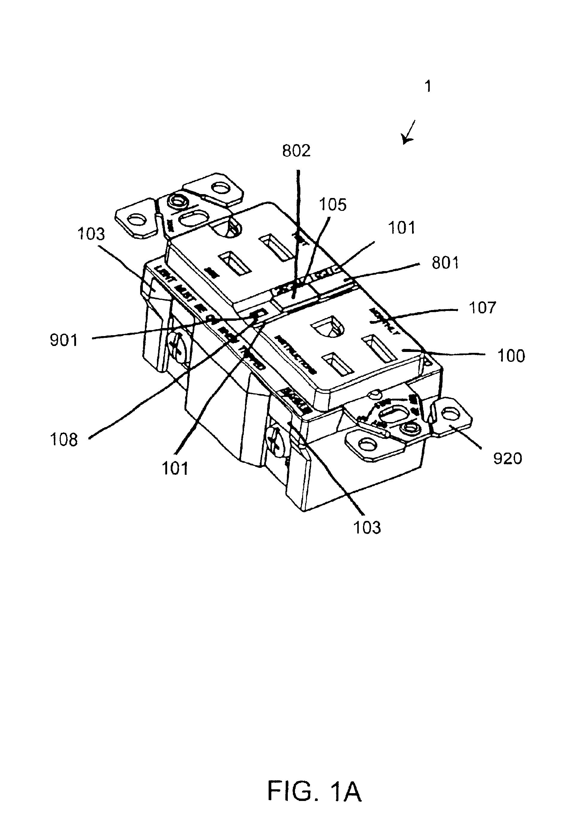
[0034]FIG. 1A shows a GFCI device 1 that is constructed in accordance with the principles of the invention. The GFCI device can have a top housing cover 100 that is constructed of a size and shape that is consistent with industry standards for an electrical outlet. Preferably, the device includes two sets of receptacle openings for receiving standard plugs. A test / reset aperture can be located along a mid-line of the top housing cover 100 and include a test button 801 and reset button 802 located therein. A light aperture 108 can also be located on the mid-line of the top housing cover 100 to enclose a light for indicating whether the GFCI device has been tripped due to either a ground fault detection or a test of the device. The light can also indicate whether the GFCI device has been correctly wired.

[0035]Top and bottom an...


PUM


Abstract

A ground fault circuit interrupter (GFCI) for opening a circuit when a ground fault has been detected in an attached circuit includes a current path structure containing no more than one splice and no more than one pair of contacts. A cantilevered movable contact arm and an activation device that moves in a linear fashion can be provided to open the current path structure when a ground fault is detected by the GFCI. In addition, the GFCI can include a transformer boat and solenoid bobbin that are snap fit onto a circuit board and located adjacent each other to provide rigidity to the circuit board and GFCI. The GFCI can be tested by a test switch that includes an integral cantilevered extension from an electrical terminal disposed over a resistor such that the cantilevered extension can be bent by a test button to contact a lead of the resistor and simulate a ground fault condition for the GFCI. Furthermore, the GFCI can include a housing with an outer portion that defines a uniform width channel adjacent a wire contact point to allow quick and easy connection to ground wires.

Description

[0001]This application is a division of application Ser. No. 09 / 251,427, filed Feb. 17, 1999, now U.S. Pat. No. 6,515,564.RELATED APPLICATION[0002]This application is related to another patent application which is commonly owned by the assignee of this application and which is incorporated by reference. The related application is: Application No. 09 / 251,426, by inventors Yuliy Rushansky and Howard S. Leopold, entitled “STANDOFF ASSEMBLY AND METHOD FOR SUPPORTING AN ELECTRICAL COMPONENT”, filed Feb. 17, 1999 and issued as U.S. Pat. No. 6,349,908 on Feb. 26, 2002.BACKGROUND OF THE INVENTION[0003]1. Field of the Invention[0004]The invention relates to an error detection circuit interrupter device that includes a detection circuit for determining whether an error has occurred in an exterior circuit and includes an interrupter device for stopping current flow to the exterior circuit when an error has been detected. More particularly, the invention relates to a ground fault circuit interr...

Claims


Application Information

Patent Timeline
Patent Type & Authority Patents(United States)
IPC IPC(8): H01H83/02H01H83/00H01H71/02H01H83/04H01H83/22
CPCH01H71/0207H01H83/02H01H83/04H01H83/226
Inventor LEOPOLD, HOWARD S.RUSHANSKY, YULLY
Owner EATON INTELLIGENT POWER LTD
Why Eureka
Try Eureka