Surface mount antenna, antenna device using the same, and communication device

a technology of surface mount antennas and antennas, applied in the direction of elongated active element feeds, resonance antennas, radiating element structural forms, etc., can solve the problems of insufficient higher-order mode resonance, difficult to independently control the fundamental mode resonance of the radiation electrode and the higher-order mode,

Inactive Publication Date: 2005-09-27
MURATA MFG CO LTD
View PDF13 Cites 66 Cited by
  • Summary
  • Abstract
  • Description
  • Claims
  • Application Information

AI Technical Summary

Benefits of technology

[0007]In order to overcome the problems described above, preferred embodiments of the present invention provide a surface mount antenna with which the resonance in the fundamental mode of a radiation electrode and that in a higher-order mode thereof can be controlled separately from each other, and thus, radio communication in plural frequency bands can be easily carried out as set in advance. In addition, preferred embodiments of the present invention provide an antenna device including such a novel surface mount antenna and a communication device including the antenna device.

Problems solved by technology

However, for example, for small-sized antennas such as surface mount antennas, it is difficult to independently control the fundamental mode resonance of the radiation electrode and the higher-order mode.
For example, there are some cases in which the fundamental mode resonance can be satisfactorily carried out, but the higher-order mode resonance is insufficient.

Method used


Image

  • Surface mount antenna, antenna device using the same, and communication device
  • Surface mount antenna, antenna device using the same, and communication device
  • Surface mount antenna, antenna device using the same, and communication device

Examples


Embodiment Construction

[0038]Hereinafter, preferred embodiments of the present invention will be described with reference to the accompanying drawings.

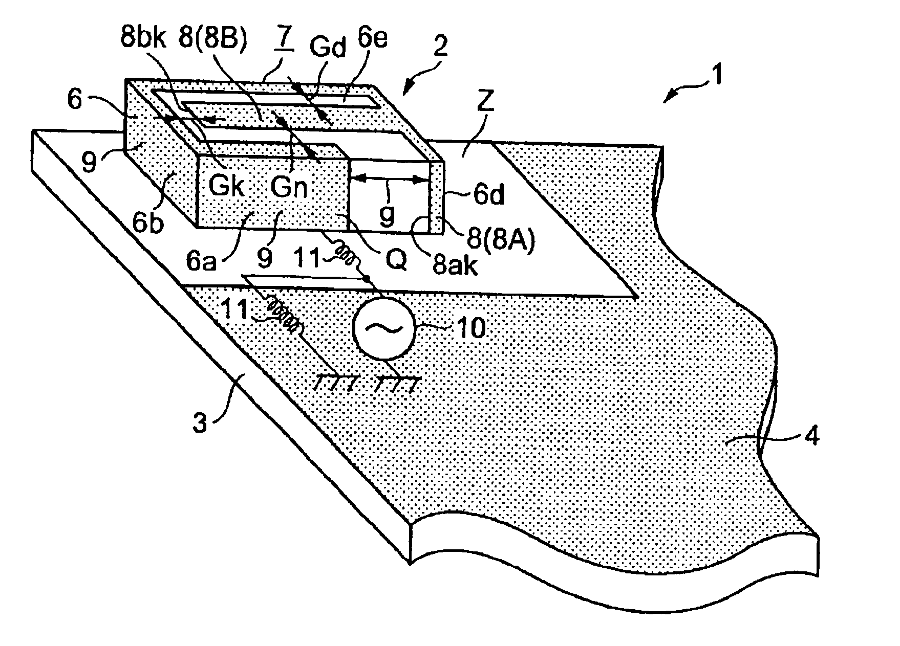
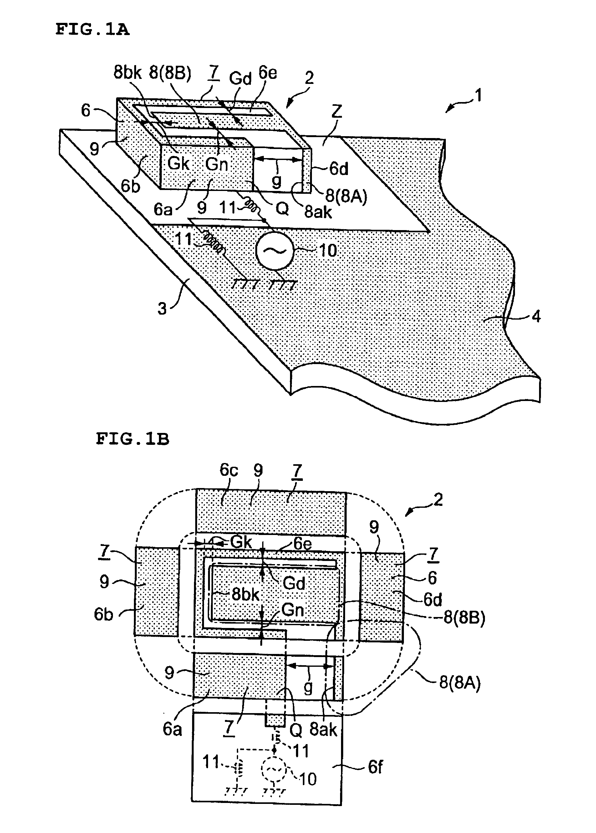
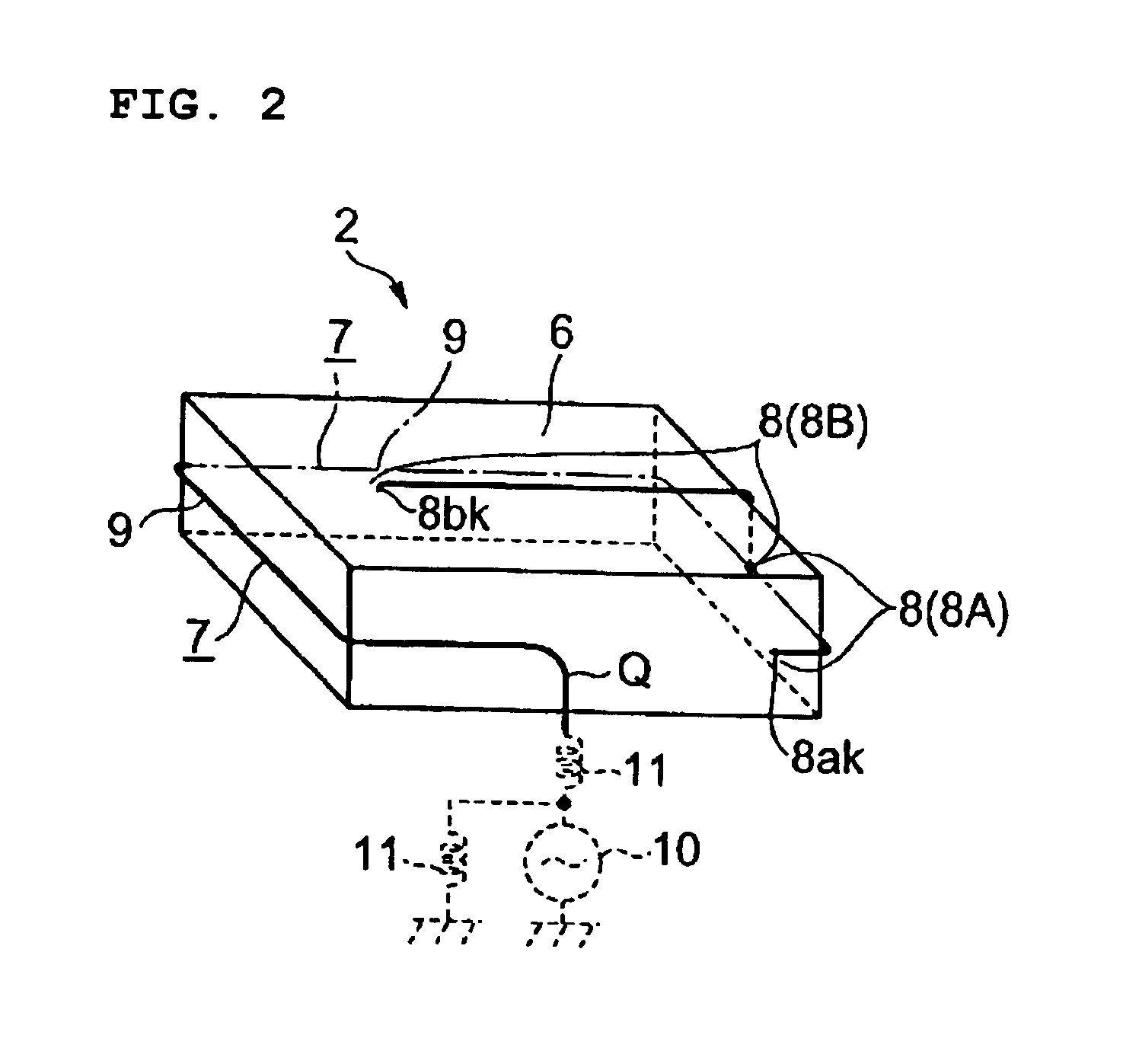
[0039]FIG. 1A is a schematic perspective view of a first preferred embodiment of a surface mount antenna and an antenna device including such an antenna. FIG. 1B is a development view of the surface mount antenna.

[0040]An antenna device 1 of the first preferred embodiment preferably includes a surface mount antenna 2 mounted on a circuit substrate 3, e.g., for use in a communication device. A ground electrode 4 is disposed on the circuit substrate 3 excluding at least the area Z in which the surface mount antenna 2 is to be mounted. Thus, the surface mount antenna 2 is surface-mounted on the non-ground area Z of the circuit substrate 3 where the ground electrode 4 is not provided.

[0041]The surface mount antenna 2 includes a substantially rectangular shaped dielectric substrate 6, and a radiation electrode 7 disposed on the substrate 6. Regarding the radiati...


PUM


Abstract

A surface mount antenna includes a loop-shaped radiation electrode arranged so as to be extended over a plurality of surfaces of a dielectric substrate. The front end side of the loop-shaped radiation electrode is branched to provide a plurality of branched radiation electrodes. One side end of the radiation electrode functions as a electric feeding portion connected to an external circuit. One of the branched radiation electrodes is an in-loop branched radiation electrode which is surrounded by a loop-shaped electrode portion including the radiation electrode portion extended from the feeding portion of the radiation electrode to a branching portion and the other branched radiation electrode connected to the radiation electrode portion, the in-loop branched radiation electrode being positioned at an interval from the loop-shaped electrode. A capacitance is generated between the one of the branched radiation electrodes and the radiation electrode portion extended from the feeding portion of the radiation electrode to the branching portion.

Description

BACKGROUND OF THE INVENTION[0001]1. Field of the Invention[0002]The present invention relates to a surface mount antenna including a radiation electrode disposed on a dielectric substrate, an antenna device including such an antenna, and a communication device[0003]2. Description of the Related Art[0004]Recently, great attention has been paid to a multi-band antenna in which radio communication can be carried out in a plurality of frequency bands by use of one antenna. For example, a radiation electrode which carries out antenna-operation has plural resonance modes having different resonance frequencies. Thus, multi-band antennas are used to perform radio communication in plural frequency bands by utilization of the plurality of resonance modes of the radiation electrode (see Japanese Unexamined Patent Application Publication No. 2002-26624 (Patent Document 1), European Patent Application Publication No. EP 0938158 A2 Specification (Patent Document 2), International Publication No. ...

Claims


Application Information

Patent Timeline
Patent Type & Authority Patents(United States)
IPC IPC(8): H01Q5/00H01Q1/38H01Q1/24H01Q5/10H01Q5/371H01Q9/40
CPCH01Q1/243H01Q5/371H01Q5/357H01Q1/38
Inventor MIYATA, AKIRAAKIYAMA, HISASHIKAWAHATA, KAZUNARI
Owner MURATA MFG CO LTD
Why Eureka
Try Eureka