
Magnetic storage medium, method for controlling track pitch thereof, and magnetic recorder for medium

a magnetic recorder and storage medium technology, applied in the direction of maintaining head carrier alignment, recording signal processing, instruments, etc., can solve the problems of reducing the number of revolutions of the magnetic disk, reducing the transfer rate of existing devices, and less efficient recording on the outer circumference compared with the inner circumference. , to achieve the effect of improving the efficiency of the recording density

Inactive Publication Date: 2005-09-27
PANASONIC CORP
View PDF9 Cites 19 Cited by
  • Summary
  • Abstract
  • Description
  • Claims
  • Application Information

AI Technical Summary

Benefits of technology

"The present invention relates to a magnetic storage medium and a method for controlling a track pitch in a disk-shaped magnetic storage medium. The technical effects of the invention include improving efficiency on recording density by setting a track pitch at an optimum value for each position in the radius direction of the storage medium, and a method for controlling a track pitch that allows for a constant ratio of a width of a guard band to a width of a track at any position in the radius direction of the storage medium. These improvements can lead to more tracks being obtained as compared with conventional devices, thereby improving yields of products. Additionally, the invention includes a configuration where data can be stored along tracks on each data surface of the storage medium, and the tracks are placed such that a ratio of the width of a guard band to the width of a track is constant at any position in the radius direction of the storage medium. This allows for efficient arrangement of the guard band at each position in the radius direction of the disk, thereby improving efficiency on recording density."

Problems solved by technology

Namely, recording is less efficient on the outer circumference as compared with the inner circumference.
However, the transfer rates of existing devices are limited because of the processing speed of a semiconductor chip such as a data channel for performing modulation and demodulation and a hard disk controller for performing serial / parallel conversion.
Further, another method is available which reduces the number of revolution of a magnetic disk and sacrifices performance to lower a transfer rate.
However, this method is hard to be a positive solution and does not remarkably match the needs of the marketplace.

Method used

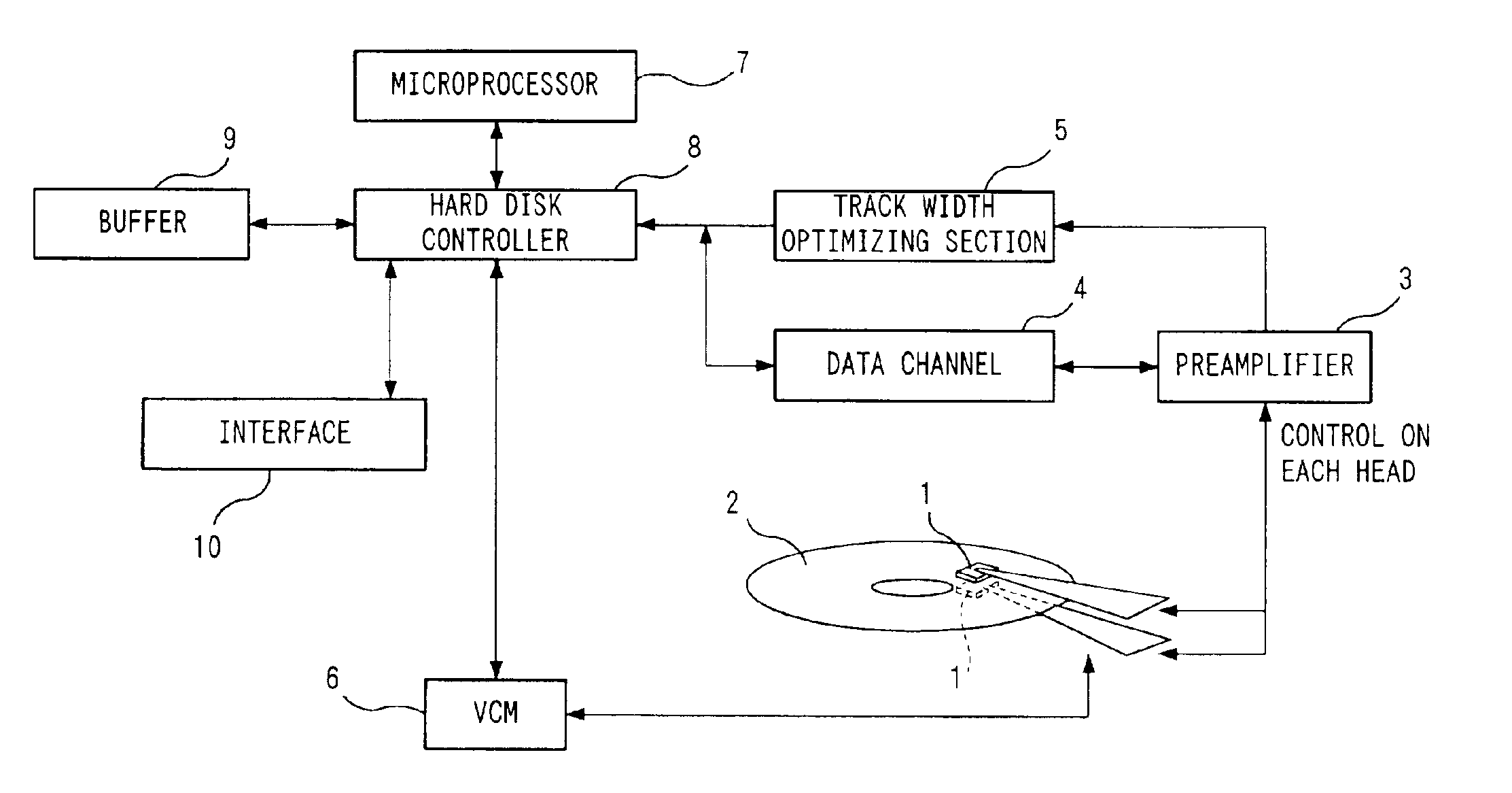
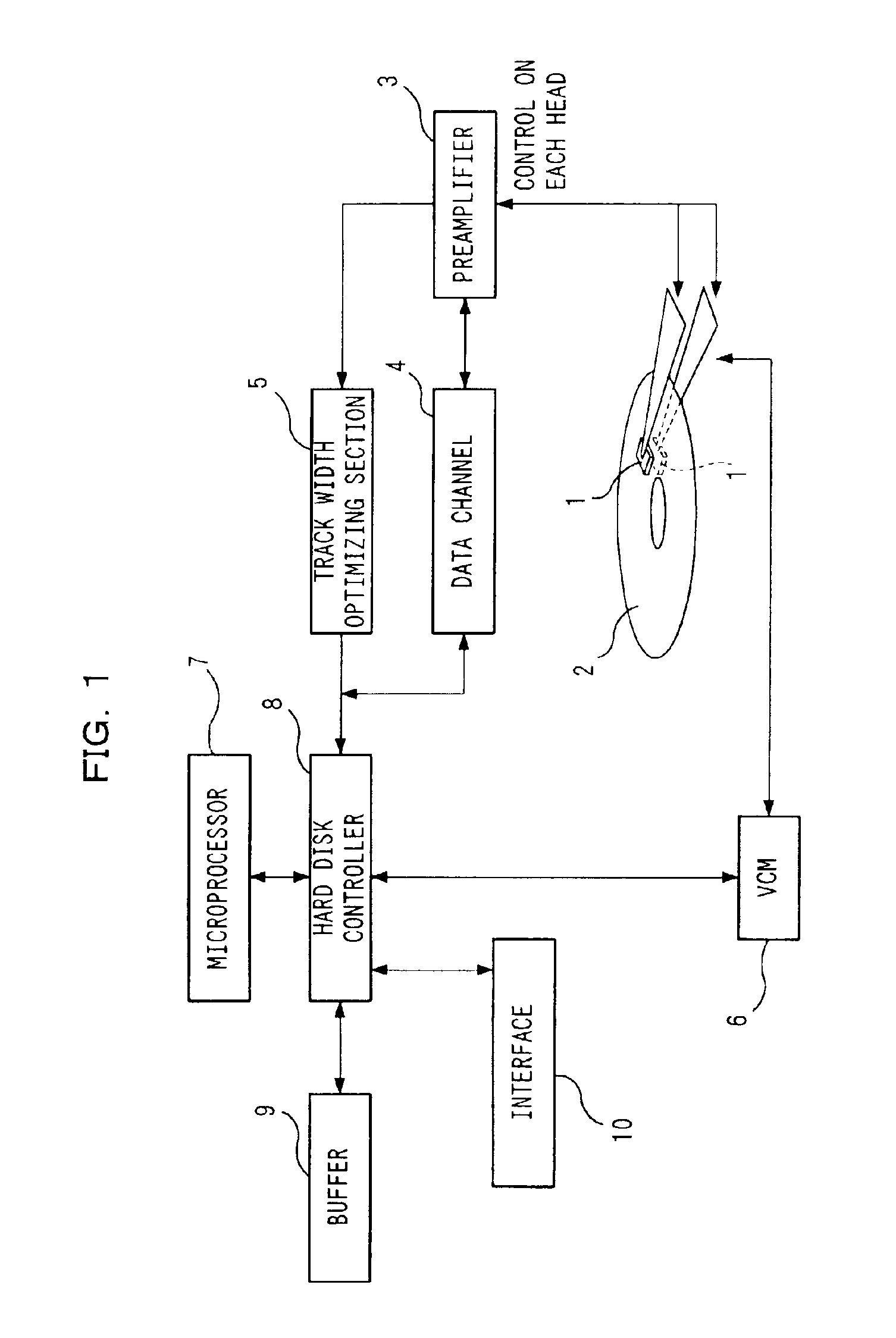

Image

  • Magnetic storage medium, method for controlling track pitch thereof, and magnetic recorder for medium
  • Magnetic storage medium, method for controlling track pitch thereof, and magnetic recorder for medium
  • Magnetic storage medium, method for controlling track pitch thereof, and magnetic recorder for medium

Examples


Embodiment Construction

[0031]Prior to explanation on embodiments of the present invention, the conventional technology of the present invention will be firstly discussed in detail.

[0032]FIG. 8 shows changes in BPI (Bit Per Inch) and TPI (Track Per Inch) as to a conventional model of a magnetic recorder. In this graph, a horizontal axis represents time and a vertical axis represents BPI / TPI ratios. According to a conventional trend, ratios of BPI and TPI (BPI / TPI) are distributed between 10 and 30, and the center is located around 20. It seems that the trend of high TPI will be widely mainstream in the future. In other words, this means that BPI / TPI ratios will be smaller and products with BPI / TPI ratios lower than 10 will appear one after another. This indicates that a recording density in the TPI direction is more likely to increase rather than the BPI direction. In order to maintain this trend, further improvement is essential on a magnetic head, a slider, a storage medium, a recording code, a servo, an...


PUM

PropertyMeasurementUnit
widthaaaaaaaaaa
widthaaaaaaaaaa
widthaaaaaaaaaa

Abstract

A magnetic storage medium is configured to store data along tracks on a disk-shaped storage medium. A distance between the tracks adjacent to each other in a radius direction of the storage medium is different depending on each position in a radius direction of the storage medium.

Description

TECHNICAL FIELD[0001]The present invention relates to a magnetic storage medium, a method of controlling a track pitch thereof, and a magnetic recorder for the medium. To be specific, the present invention relates to a TPI optimizing method for a track pitch direction (radius direction of a magnetic disk as a magnetic storage medium) in a fixed magnetic recorder, which uses a positioning mechanism including a magnetic recording / reproducing head of a rotary (swing arm) method, concerns a fixed magnetic recorder using the optimizing method, and a magnetic disk thereof.BACKGROUND ART[0002]In recent years, most fixed magnetic recorders (HDD: hard disk drive) have improved in various element technologies in response to increasing demand for higher recording density. Decisive elements for determining a recording density of a HDD include a magnetic head, a storage medium, a recording / reproducing channel, and a positioning mechanism. In order to maintain further improvement of recording den...

Claims


Application Information

Patent Timeline
Patent Type & Authority Patents(United States)
IPC IPC(8): G11B20/10G11B20/20G11B20/12G11B5/58G11B5/596G11B5/012G11B5/02G11B21/10
CPCG11B5/581G11B5/59611G11B20/10G11B20/1258G11B20/20G11B5/012G11B2020/1238G11B2020/1277G11B2020/1292G11B2220/2516G11B5/29G11B5/4886G11B2005/3996
Inventor KADOKAWA, KOUICHI
Owner PANASONIC CORP
Learn More