Adaptive duty cycle management method and system for radio transmitters

Active Publication Date: 2005-09-27
CALAMP CORP
View PDF10 Cites 24 Cited by
  • Summary
  • Abstract
  • Description
  • Claims
  • Application Information

AI Technical Summary

Benefits of technology

[0011]Advantageously, the invention provides for a wireless transmission not exceeding an established duty cycle limit based on short fixed-length windows of time, while permitting longer transmission times in the form of bursts in order to

Problems solved by technology

However, transmission of the packet is delayed when the counter amount has reached that maximum counter amount (viz. t

Method used


Image

  • Adaptive duty cycle management method and system for radio transmitters
  • Adaptive duty cycle management method and system for radio transmitters
  • Adaptive duty cycle management method and system for radio transmitters

Examples


Embodiment Construction

[0019]The following description is of an example of a preferred embodiment of the invention which is provided only for purposes of illustration and without any intention to limit the invention to this particular example or to any particular duty cycle limit.

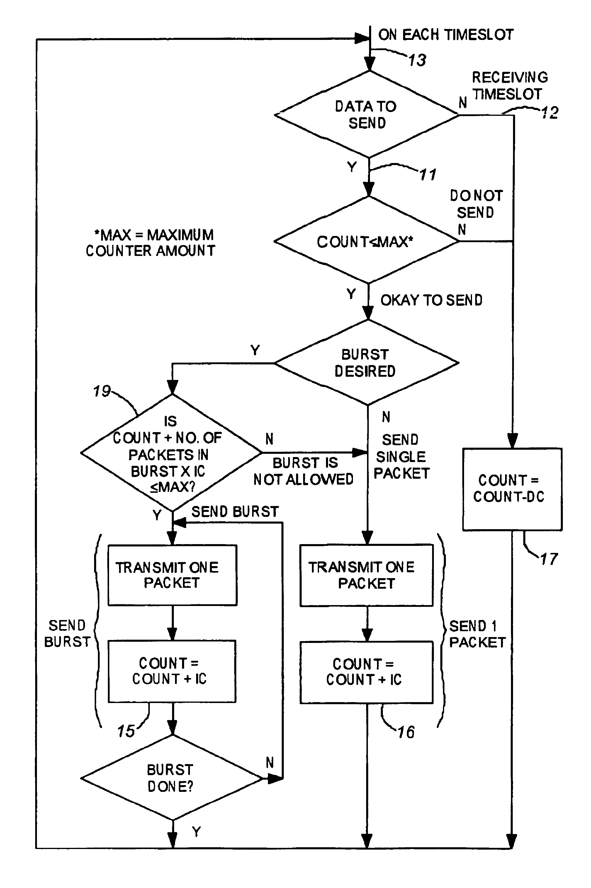
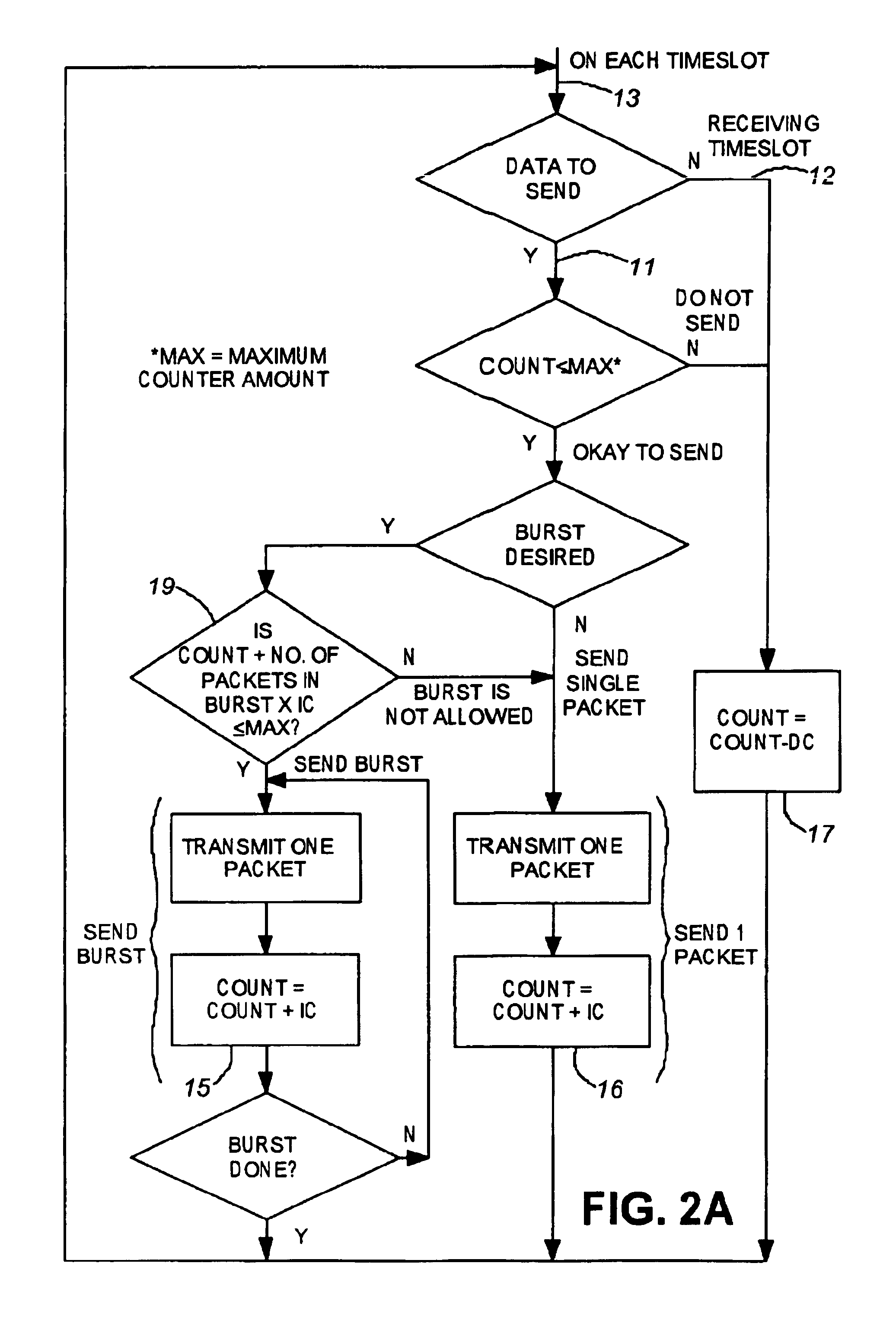
[0020]In digital wireless transmission, the transmitter circuitry modulates a carrier signal with a digital signal comprised of data packets. The transmission of the modulated data packets is typically performed according one of two modes being that of individual packets or bursts of packets. Each packet comprises address, data, sender identification and control portions and instead of being transmitted continuously they are stored until an individual packet, or a group of packets is ready for transmission. Therefore, the output power generated by the transmitter follows a pattern of short intervals in order to transmit bursts (being groups of packets) coupled with relatively long periods of quiet time (also referred to as idle t...


PUM


Abstract

A duty cycle management system and method for use in a wireless device having a transmitter which transmits packets in the form of individual packets and/or packet bursts. A controller in combination with an instruction set limits the number of packets transmitted during each time period defined by one time window or adjacent time windows, on a sliding basis, so as to limit the duty cycle of transmissions during successive adjacent time windows to the predetermined duty cycle limit. To do so transmission of packets is delayed as needed to establish sufficient idle period(s) during the one or adjacent time window(s) to maintain the duty cycle within the duty cycle limit.

Description

FIELD OF INVENTION[0001]The present invention is directed to management of the duty cycle of wireless data transmissions and, in particular, to an adaptive duty cycle management method and system for digital radio frequency (RF) transmitters which limit the duty cycle on a sliding window basis to a preselected maximum amount.BACKGROUND OF THE INVENTION[0002]There exists a concern regarding the safety to users of wireless communications devices, such as mobile radios and cellular telephones, when these devices are operated in their transmit mode by reason that it is perceived the electromagnetic radiation associated with the transmission of the signals from such devices may pose a potential health hazard to the user. When using a hand-held wireless device the user holds the device near the ear and this positions the devices transmission antenna in close proximity to the user's hand and head as it transmits electromagnetic radiation and it is postulated that a portion of this radiatio...

Claims


Application Information

Patent Timeline
IPC IPC(8): H04L12/56H04B1/02H04B1/036H04B1/38H04L1/16H04L1/18
CPCH04B1/036H04B1/3838H04L1/1854H04W28/10H04W28/18
Inventor PEARL, NORMAN
Owner CALAMP CORP
Why Eureka
Try Eureka