Video coding by adaptively controlling the interval between successive predictive-coded frames according to magnitude of motion

Inactive Publication Date: 2005-09-27
NEC CORP +1
View PDF11 Cites 22 Cited by
  • Summary
  • Abstract
  • Description
  • Claims
  • Application Information

AI Technical Summary

Benefits of technology

[0010]It is therefore an object of the present invention to provide a video coding apparatus and method

Problems solved by technology

Therefore, if unidirectional (forward) predictive coding were exclusively used, predictive coded “generations” would increase rapidly with time and quantization errors would accumulate significantly.
Although the B-picture provides a benefit, the use of many B-pictures (with the resultant increase in the M-value) is disadvantageous for fast-moving pictures since it becomes difficult to search for motion vectors within a range that is considered appropriate.
However, a significant amount of hardware is necessary to implement this approach.
Although the hardware problem can be avoided by the use of an algorithm that simplifies motion vector search, this would be only achieved

Method used


Image

  • Video coding by adaptively controlling the interval between successive predictive-coded frames according to magnitude of motion
  • Video coding by adaptively controlling the interval between successive predictive-coded frames according to magnitude of motion
  • Video coding by adaptively controlling the interval between successive predictive-coded frames according to magnitude of motion

Examples


Embodiment Construction

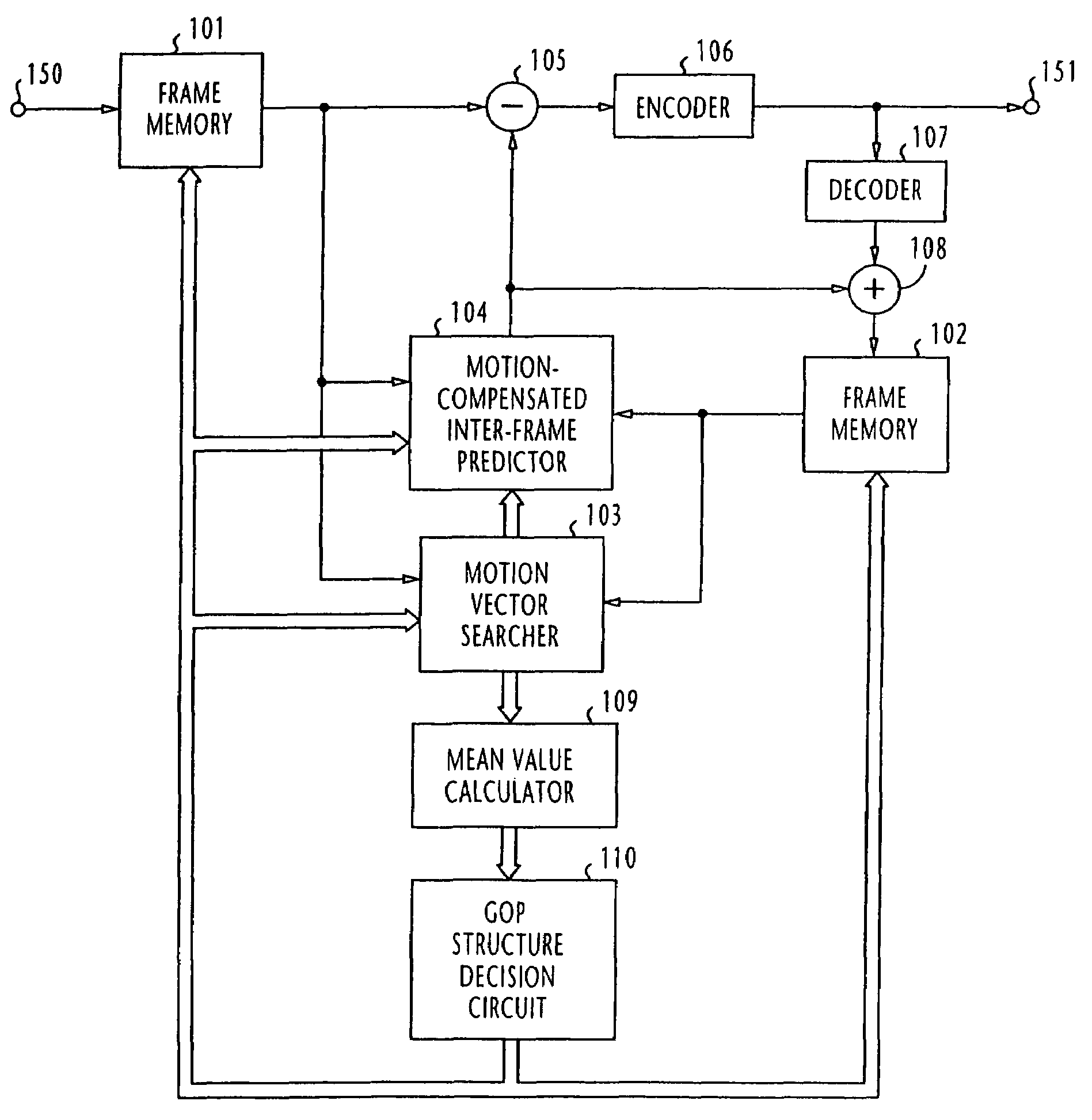
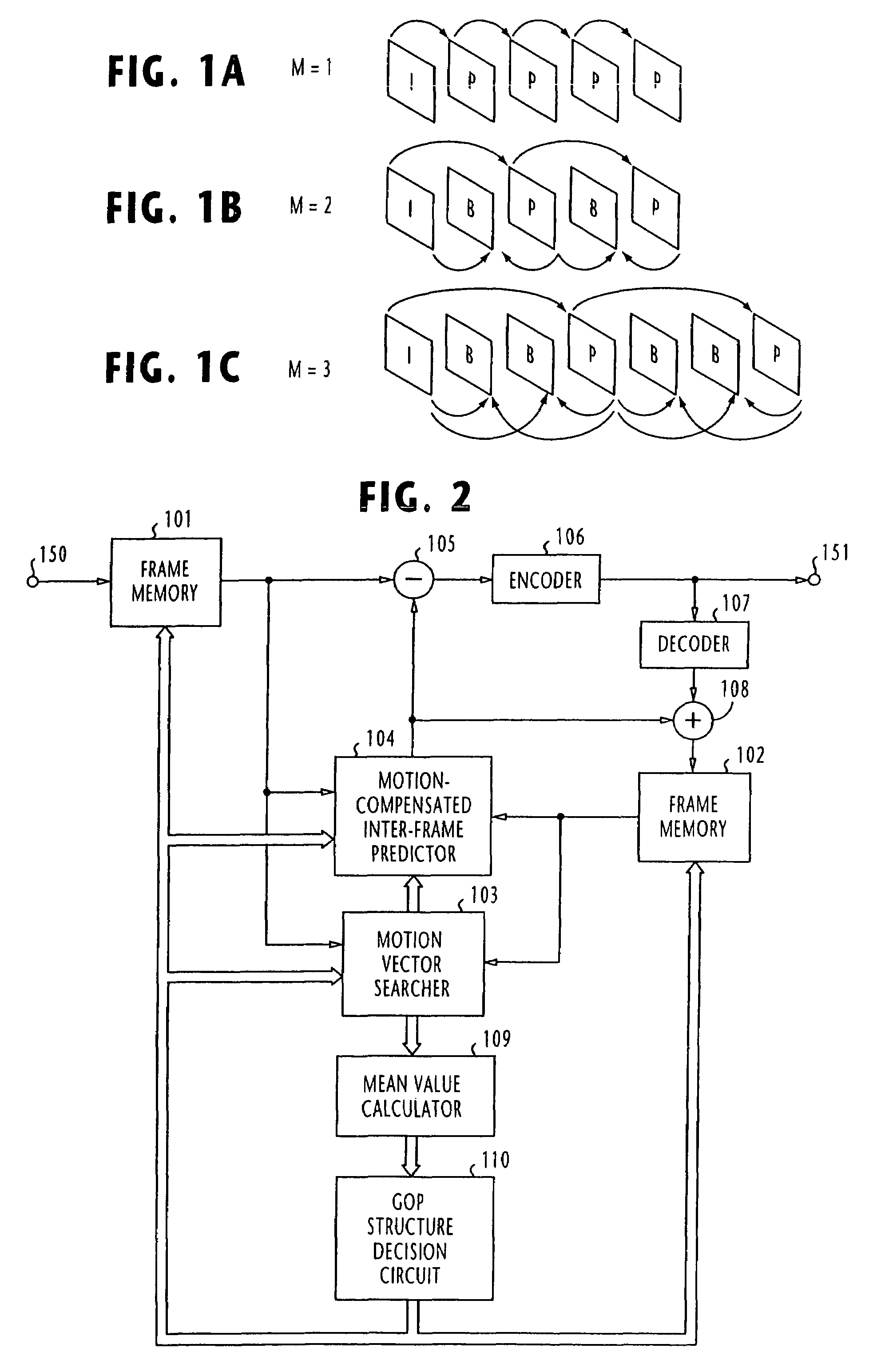
[0023]Referring to FIG. 2, there is shown a video coding apparatus according to the present invention. The coding apparatus is comprised of an input frame memory 101 for receiving a plurality of video frames supplied from an input terminal 150 for storage and outputting frames in a coding order in which these output frames will be encoded. Each of the stored frames is divided into a plurality of regions or “macroblocks” and a coding process will be performed on each of the macroblocks. The reordering of the frames in the input frame memory 101 is controlled by a GOP structure decision circuit 110 which produces an M-value representing a GOP (group of pictures) structure. A differential signal representing the error between a predicted frame provided by an motion-compensated inter-frame predictor 104 and a frame supplied from memory 101 is produced by a subtractor 105. This prediction error is coded by an encoder 106 and supplied to an output terminal 151.

[0024]The output of encoder ...


PUM


Abstract

In a video coding apparatus, coding/decoding circuitry provides motion-compensated inter-frame prediction coding on input frames by using reference frames so that the input frames are coded into an intra-frame coded picture, a predictive coded picture or a bi-directionally predictive coded picture and decoding the coded frames to produce reference frames. Decision circuitry determines the magnitude of motion of the input frames relative to the reference frames, determines the interval between successive frames of the predictive coded picture according to the determined magnitude of motion and reorders the input frames according to the determined interval.

Description

BACKGROUND OF THE INVENTION[0001]1. Field of the Invention[0002]The present invention relates to a video coding apparatus and method for encoding moving pictures in a compressed format according to an international standard such as ISO / IEC 13818-2, known as MPEG-2.[0003]2. Description of the Related Art[0004]The MPEG-2 standard defines three picture types: intra-coded pictures (I-pictures), predictive coded pictures (P-pictures) and bi-directionally predicted pictures (B-pictures). I-pictures are coded in such a way that they can be decoded without knowing anything about other pictures in a video sequence. The first picture in a group of pictures is always an I-picture and provides key information for pictures that follow. P-pictures are coded (i.e., forward predictive coded) by using information from a reference picture displayed earlier, which may be either an I-picture or a P-picture. B-pictures also use information from pictures displayed earlier and from pictures coming in the ...

Claims


Application Information

Patent Timeline
IPC IPC(8): H04N7/32H04N7/12H04N11/00H04N11/02H04N19/50H04N5/14H04N19/102H04N19/103H04N19/105H04N19/12H04N19/134H04N19/139H04N19/172H04N19/176H04N19/196H04N19/503H04N19/51H04N19/513H04N19/57H04N19/593H04N19/61H04N19/625H04N19/91
CPCH04N5/145H04N19/139H04N19/159H04N19/172H04N19/114H04N19/137
Inventor YOKOYAMA, YUTAKAOOI, YASUSHI
Owner NEC CORP
Why Eureka
Try Eureka