
Precision timing generator apparatus and associated methods

a generator and precision technology, applied in the field of radio systems, can solve the problems of limiting the effectiveness of the communication channel, the accuracy with which the pulses can be positioned, and the resolution of existing systems,

Inactive Publication Date: 2005-09-27
ALEREON
View PDF24 Cites 90 Cited by
  • Summary
  • Abstract
  • Description
  • Claims
  • Application Information

AI Technical Summary

Benefits of technology

[0012]This invention contemplates precision timing generators and associated methods that overcome the problems present in the prior art. One aspect of the invention relates to-precision timing generator a

Problems solved by technology

One factor limiting the effectiveness of the communication channel is the accuracy with which the pulses can be positioned.
Limitations in resolution of existing systems are partially a result of the limitations in the ability to encode a transmitted signal with a precisely timed sequence.
Generating such high precision pulses, however, is quite difficult.
Currently available analog or digital integrated circuit timers are not capable of creating such high precision pulses.
Typical impulse radio timer systems are relatively complex, expensive, board level devices that are difficult to produce.

Method used


Image

  • Precision timing generator apparatus and associated methods
  • Precision timing generator apparatus and associated methods
  • Precision timing generator apparatus and associated methods

Examples


Embodiment Construction

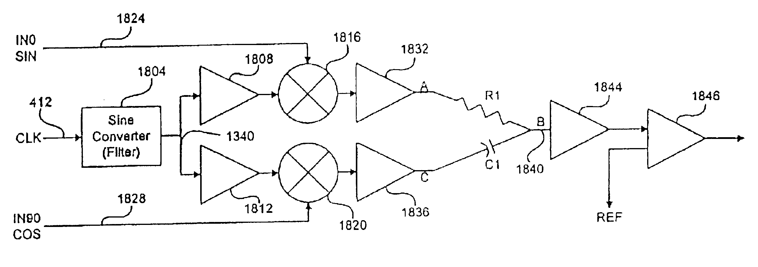
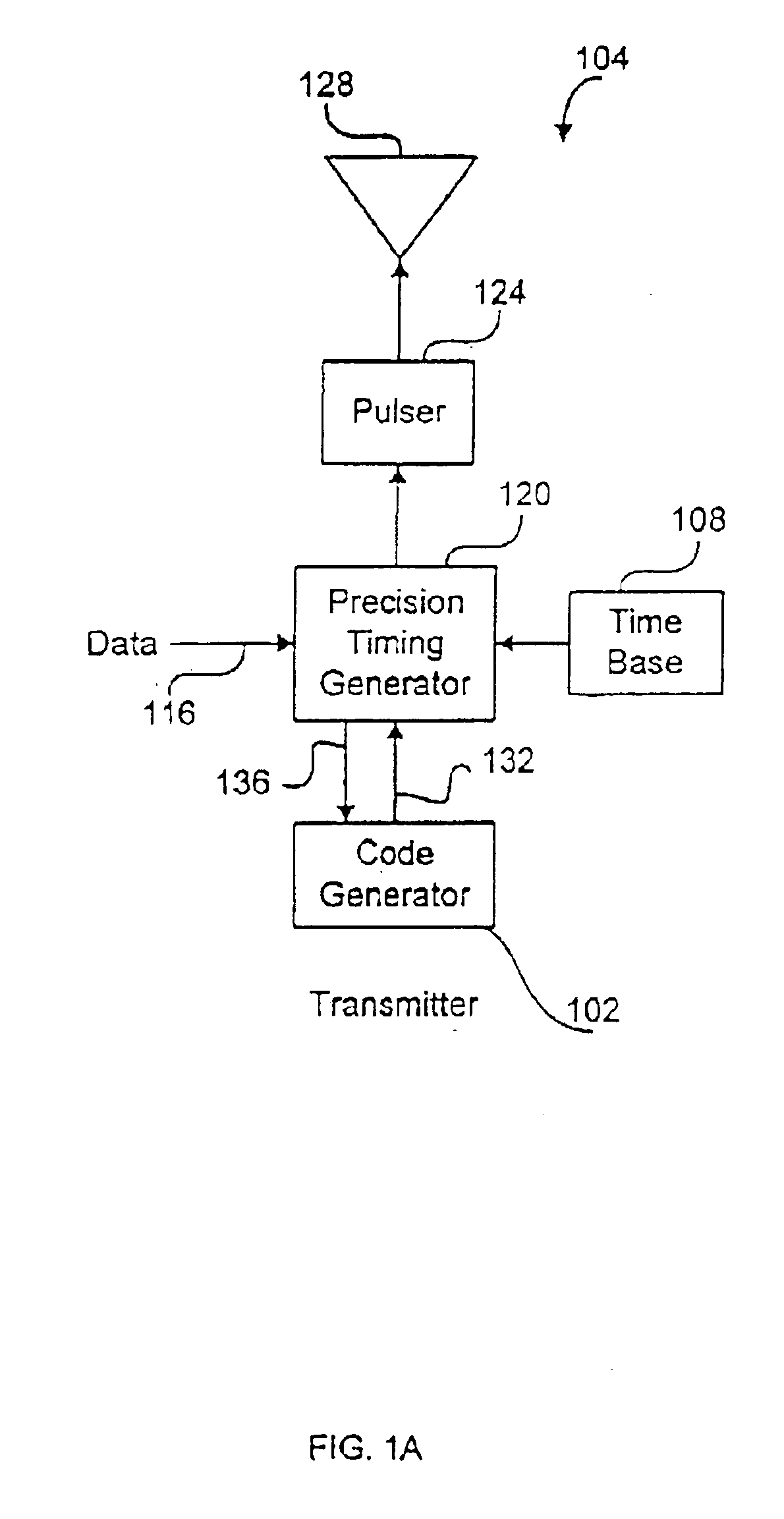
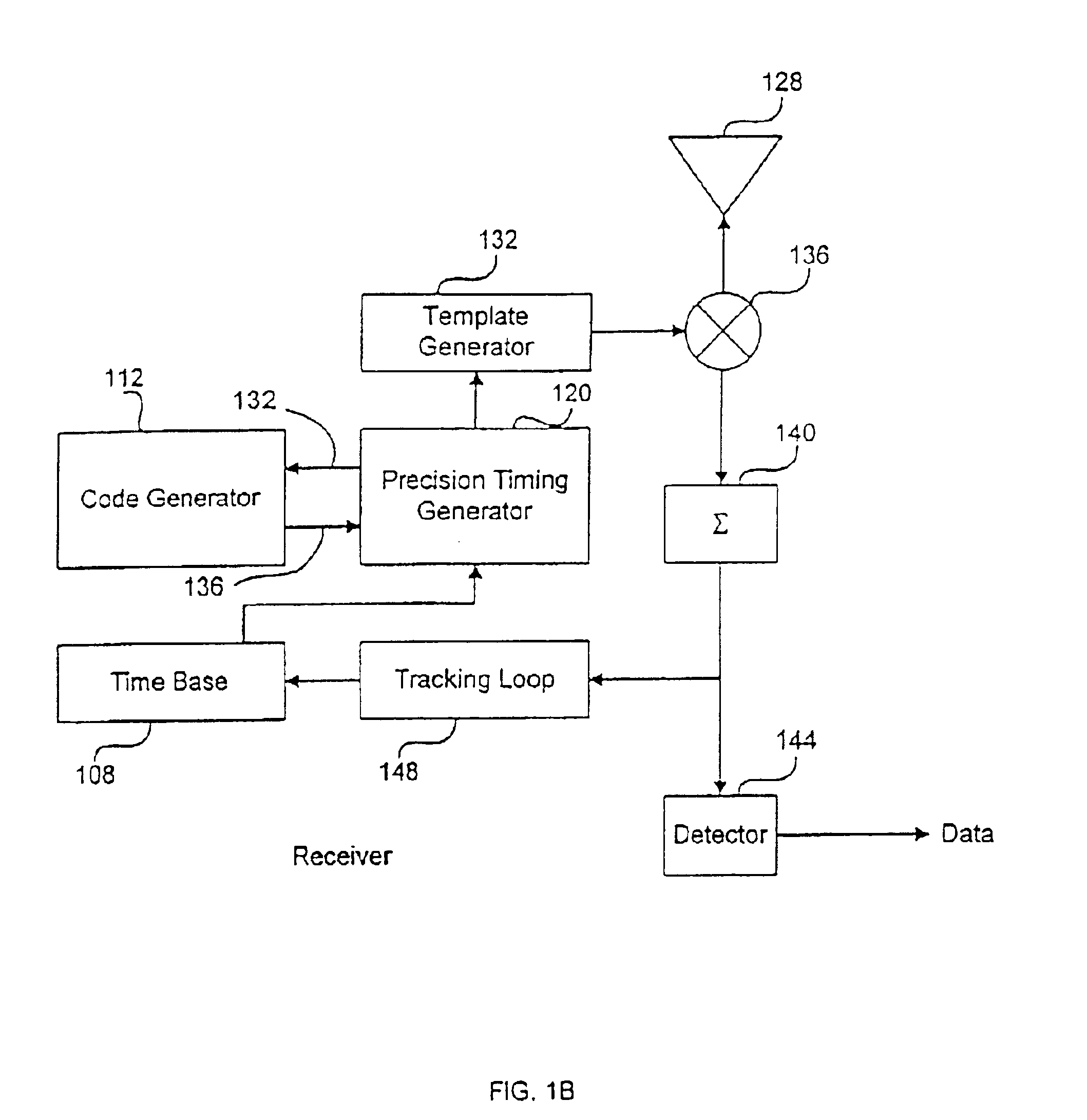
[0056]The present invention is directed to a system and method for generating highly agile and precise timing signals as are typically required for impulse radio systems. According to the invention, a coarse timing generator is utilized to generate a coarse timing signal at a coarse time interval within a nominal frame interval. A fine timing generator, synchronized to the coarse timing generator, provides a set of fine time intervals that interpolate between coarse time intervals. A combining circuit utilizes the coarse timing signal to select the correct fine timing signal that drives the output. This system is typically phase locked to a stable reference oscillator source, which provides good long term drift performance. In an exemplary application, this system is capable of providing timing for near 10 ps positioning of sub-nanosecond pulses with in a 100 ns frame with less than 50 ns setup time. This timing is needed for pseudo random code positioning of pulses in impulse radio...


PUM


Abstract

A precision timing generator includes a combiner that provides a timing signal by combining a coarse timing signal and a fine timing signal derived from a phase-shifted sinusoidal signal that has a desired phase shift. The coarse timing generator generates the coarse timing signal from a clock signal and a timing command input. The fine timing generator includes a sinusoidal-signal generator that receives the clock signal and generates a sinusoidal signal. The fine timing generator also includes a phase shifter that receives the sinusoidal signal and the timing command input and shifts the phase of the sinusoidal signal based on the timing input to generate the phase shifted sinusoidal signal.

Description

CROSS-REFERENCE TO RELATED APPLICATIONS[0001]The present patent application is a continuation of U.S. patent application Ser. No. 09 / 910,178, titled “Precision Timing Generator Apparatus and Associated Methods,” filed on Jul. 20, 2001, now U.S. Pat. No. 6,577,691, which is a continuation-in-part of U.S. patent application Ser. No. 09 / 146,524, titled “Precision Timing Generator System and Method,” filed on Sep. 3, 1998, now U.S. Pat. No. 6,304,623. and assigned to the assignee of the present patent application.TECHNICAL FIELD OF THE INVENTION[0002]This invention generally relates to radio systems and, more specifically, to a precision timing generator for impulse radio technologies, such as communication systems, radar, and security systems.BACKGROUND[0003]Recent advances in communications technology have enabled communication systems to provide ultra-wideband communication systems. Among the numerous benefits of ultra-wideband communication systems are increased channelization, resi...

Claims


Application Information

Patent Timeline
IPC IPC(8): H04L7/00H03L7/00G01S7/282G01S13/02G01S13/10H03D3/24H03K5/135H03L7/18H04BH04B1/69H04B14/02H04J3/06H04L1/08H04L7/08H04L25/40
CPCG01S7/282G01S13/0209G01S13/106H03L7/18H04B1/71635H04B1/7183H04L1/08
Inventor RICHARDS, JAMES L.JETT, PRESTON L.FULLERTON, LARRY W.LARSON, LAWRENCE E.ROWE, DAVID A.
Owner ALEREON
Learn More