Hollow core photonic bandgap optical fiber

a photonic bandgap and optical fiber technology, applied in the field of optical fibers, can solve the problems of large loss, use total internal reflection like a conventional optical fiber, etc., and achieve the effect of high reflection coefficien

Inactive Publication Date: 2005-09-27
MICRON TECH INC
View PDF10 Cites 9 Cited by
  • Summary
  • Abstract
  • Description
  • Claims
  • Application Information

AI Technical Summary

Problems solved by technology

Though optical fiber 210 is photonic crystal based, it utilizes total internal reflection like a conventional optical fiber and is relatively lossy because the solid core absorbs radiation.

Method used


Image

  • Hollow core photonic bandgap optical fiber
  • Hollow core photonic bandgap optical fiber
  • Hollow core photonic bandgap optical fiber

Examples


Embodiment Construction

[0029]In the following detailed description of the embodiments of the invention, reference is made to the accompanying drawings that form a part hereof, and in which is shown by way of illustration specific embodiments in which the invention may be practiced. These embodiments are described in sufficient detail to enable those skilled in the art to practice the invention, and it is to be understood that other embodiments may be utilized and that changes may be made without departing from the scope of the present invention. The following detailed description is, therefore, not to be taken in a limiting sense, and the scope of the present invention is defined only by the appended claims.

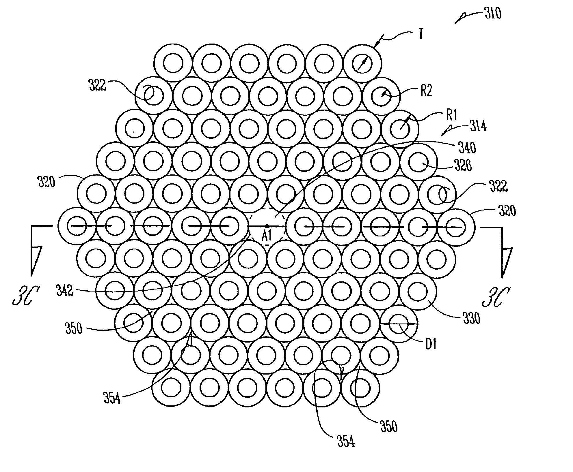
[0030]FIG. 3A is a full front-end view of an embodiment of a hollow core photonic bandgap optical fiber 310 of the present invention. Optical fiber 310 includes an array 314 of conventional hollow core optical fibers 320 each longitudinally arranged about a central axis A1. Optical fibers 320 each havi...


PUM

PropertyMeasurementUnit
effective diameteraaaaaaaaaa
dielectric constant ∈Baaaaaaaaaa

Abstract

A photonic crystal optical fiber made up of an array of conventional hollow core optical fibers is disclosed. The array of optical fibers omits at least one fiber to form a central hollow core. The fiber works on the principle of two-dimensional photonic crystals to confine the radiation in a guided wave within the central hollow core. The fiber has a true photonic bandgap in which radiation of a particular energy or wavelength is totally forbidden, thereby providing a very high reflection coefficient to radiation incident the walls of the central hollow core over a select range of angles. The central hollow core allows for radiation propagation with minimal absorption.

Description

RELATED APPLICATION[0001]This application is a continuation of U.S. application Ser. No. 10 / 099,044 filed on Mar. 13, 2002, now U.S. Pat. No. 6,829,421 and incorporated herein by reference.FIELD OF THE INVENTION[0002]The present invention relates to optical fibers, and in particular to a hollow core photonic bandgap optical fiber.BACKGROUND OF THE INVENTION[0003]Optical fibers are long, thin waveguide strands. They are used in a variety of applications involving the reception, transmission and detection of radiation, ranging from optical telecommunications to scientific instrumentation to ornamental displays. Conventional optical fibers have a high-index core surrounded by a low-index cladding, a geometry that results in the total internal reflection of radiation entering the fiber over a select range of angles. Other forms of conventional optical fibers are referred to as “light tunnels” and use reflection from reflective walls rather than total internal reflection. Conventional op...

Claims


Application Information

Patent Timeline
Patent Type & Authority Patents(United States)
IPC IPC(8): C03B37/012C03B37/10C03B37/15G02B6/02
CPCC03B37/01205C03B37/0124C03B37/15G02B6/02328G02B6/02347G02B6/02371C03B2203/14C03B2203/16C03B2203/42
Inventor FORBES, LEONARDGEUSIC, JOSEPH E.
Owner MICRON TECH INC
Why Eureka
Try Eureka