Hanger bearing for auger type poultry chiller with cone deflector

a technology of bearings and chillers, which is applied in the field of hanger bearings, can solve the problems of affecting affecting the efficiency of the chiller, so as to achieve the effect of speeding up or slowing down the speed of the chiller

Inactive Publication Date: 2005-10-04
MORRIS & ASSOCS
View PDF13 Cites 18 Cited by
  • Summary
  • Abstract
  • Description
  • Claims
  • Application Information

AI Technical Summary

Benefits of technology

[0009]Briefly described, this invention involves a poultry chiller that includes a hanger bearing assembly for use in supporting a segmented auger of an auger type poultry chiller. The novel hanger bearing assembly allows smaller gaps to be formed between the segments of the auger. The smaller gap between the auger segments reduces the tendency of birds moving from the first auger blade to the second auger blade to be deflected rearwardly in a direction counter to that intended.

Problems solved by technology

One of the problems of existing hanger bearings 30 is that the interruption of the helical blade structure at the intermediate bearing location impedes the forward movement of birds through the poultry chiller.
The reverse movement of these birds tends to create, or increase, the size of product surges traveling through the poultry chiller.
The surges result in uneven unloading of the birds at the outlet end of the chiller, causing personnel handling the birds at the outlet end of the chiller to either speed up or slow down depending upon the output of birds from the chiller.
In some cases, surges can require the addition of extra handling personnel.
In those instances where personnel are not available, it is not uncommon for the birds to back up in the chiller discharge chute, causing birds to spill over the sides of the chute and handling tables positioned at the outlet end of the chiller.
However, for those plants that do not have additional handling personnel, or that don't respond quickly enough to the surges, the birds will frequently fall to the plant floor, leading to lost product and unsanitary conditions.
Another problem with typical hanger bearings is that the relatively large spacing required between independent segments of the helical flight structure (approximately 10 inches and up) allows birds to remain in the poultry chiller after processing is complete.
Removal of the stranded birds increases the time required to clean the poultry chiller, thereby increasing the down time for cleaning the chiller.
In addition to increased time and expense associated with the clean-up process, expense is incurred due to loss of product at the hanger bearing.
Longer chillers require more hanger bearings to support the auger, thereby resulting in more frequent surging and increase product loss.
Thus, a heretofore unaddressed need exists in the industry to address the aforementioned deficiencies and inadequacies.

Method used


Image

  • Hanger bearing for auger type poultry chiller with cone deflector
  • Hanger bearing for auger type poultry chiller with cone deflector
  • Hanger bearing for auger type poultry chiller with cone deflector

Examples


Embodiment Construction

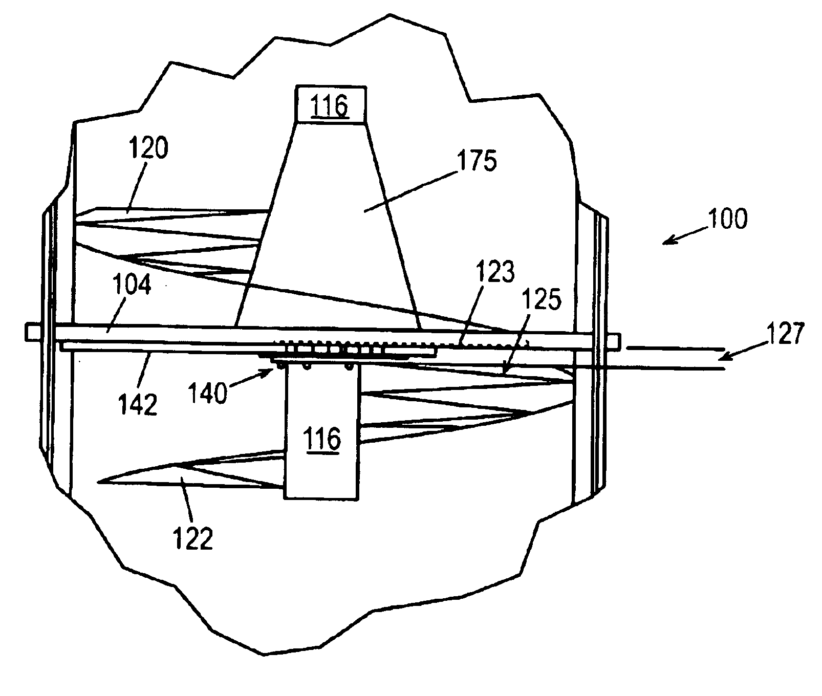
[0028]Referring now in more detail to the drawings, in which like numerals indicate like parts throughout the several views, FIG. 4A illustrates a cross-sectional view of the poultry chiller 100 as viewed from the inlet end. The poultry chiller 100 includes a semi-cylindrical water reservoir, or tank 102, a support member 104 connected to the tank 102, and an auger 110 supported at opposing ends by the tank 102.

[0029]The auger 110 is positioned longitudinally in the tank 102. An electric motor or other conventional power means (not shown) is provided to rotate the auger 110. The auger 110 includes an auger shaft 112 and a helical blade structure formed around the shaft 112. As shown in FIG. 4B, the auger shaft 112 includes at least a first auger shaft segment 114 and a second auger shaft segment 116. The helical blade structure includes a first flight segment 120 formed around the first auger shaft segment 114 and a second flight segment 122 formed around the second auger shaft segm...


PUM


Abstract

A poultry chiller 100 has a hanger 140 suspended from the upper portion of the tank 102 that supports the bearing block 160 of the auger shaft 112 between the auger blades. A conical bird deflector 175 is mounted on the auger shaft and radially deflects the birds away from the bearing block as the birds are urged across the bearing block.

Description

CROSS REFERENCE[0001]This is a continuation-in-part of U.S. patent application Ser. No. 10 / 336,273, filed Jan. 3, 2003, now U.S. Pat. No. 6,722,490.TECHNICAL FIELD[0002]The present invention generally relates to poultry chillers for reducing the temperature of whole birds after the birds have been eviscerated on a poultry processing line. More particularly, the invention relates to a hanger bearing assembly configured to support an auger within the poultry chiller.BACKGROUND OF THE INVENTION[0003]It is desirable to reduce the temperature of chickens and other type poultry after the birds have been processed, or de-feathered, eviscerated, and are otherwise oven-ready and before the birds are packaged for delivery to the retail customer. A conventional poultry chiller 10, as shown in FIG. 1, is the “auger type” poultry chiller 10 which includes a trough-shaped, half-round tank 12 filled with ice water in which the auger 20 provides positive movement of the birds through the tank 12. T...

Claims


Application Information

Patent Timeline
Patent Type & Authority Patents(United States)
IPC IPC(8): A23B4/06A23B4/09A23L3/375A23L3/36A22C21/00B65G33/00B65G33/32F16C17/00F28F5/00F16C17/10F25D13/00F25D13/06
CPCA22C21/0053A23B4/062A23B4/064A23B4/09A23L3/361A23L3/375B65G33/32F16C17/10F28F5/00F25D13/065
Inventor BASS, GREGORY T.
Owner MORRIS & ASSOCS
Why Eureka
Try Eureka