
Tissue closure treatment system and method with externally-applied patient interface

a technology of tissue closure and patient interface, applied in the field of tissue closure treatment system and patient interface with external application, can solve the problems of tissue separation, dead space problems that are more apt to occur, and incisions that require multiple layers of sutures, and achieve the effect of enhancing the closure of separated tissue portions

Inactive Publication Date: 2005-10-04
3M INNOVATIVE PROPERTIES CO
View PDF116 Cites 569 Cited by
  • Summary
  • Abstract
  • Description
  • Claims
  • Application Information

AI Technical Summary

Benefits of technology

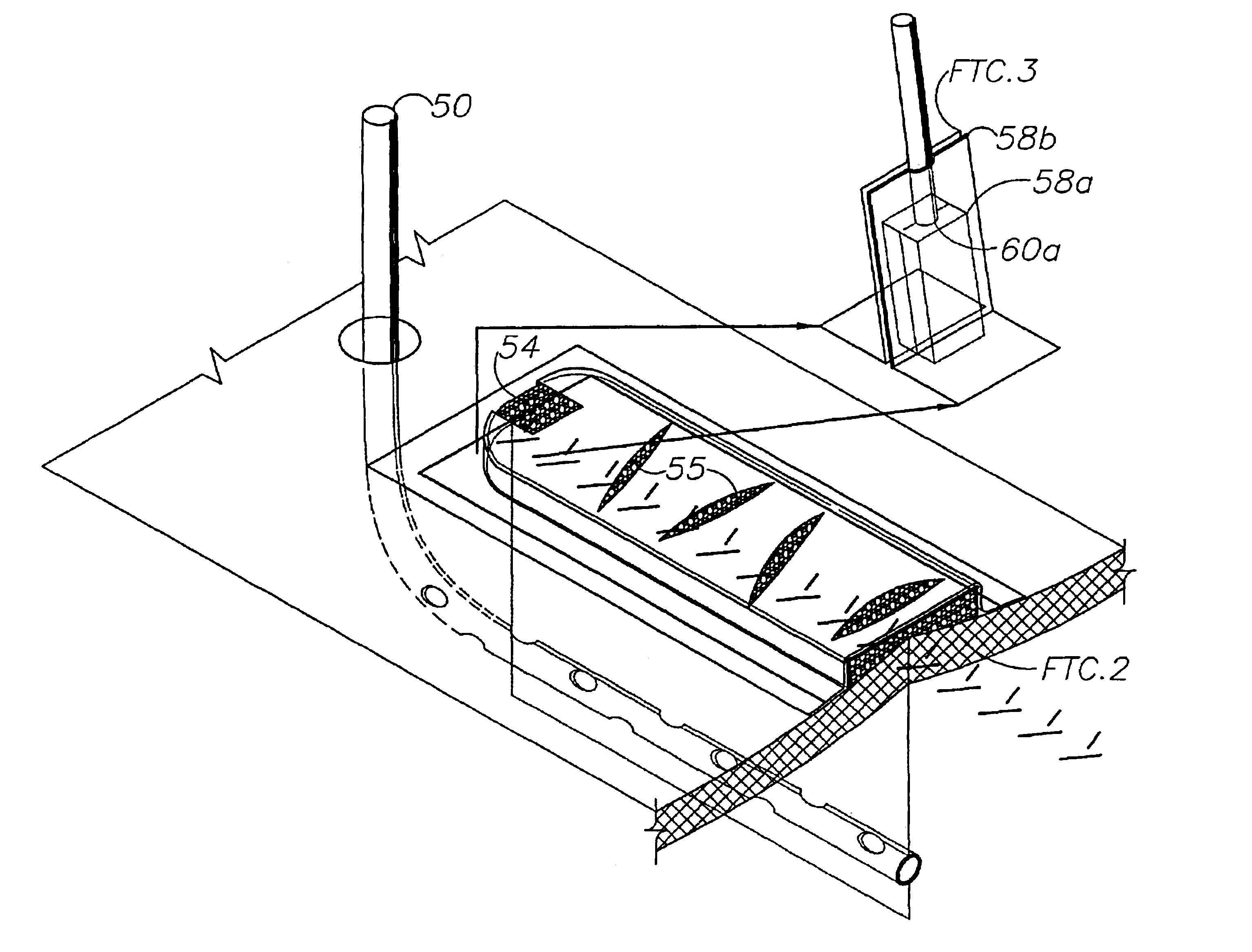
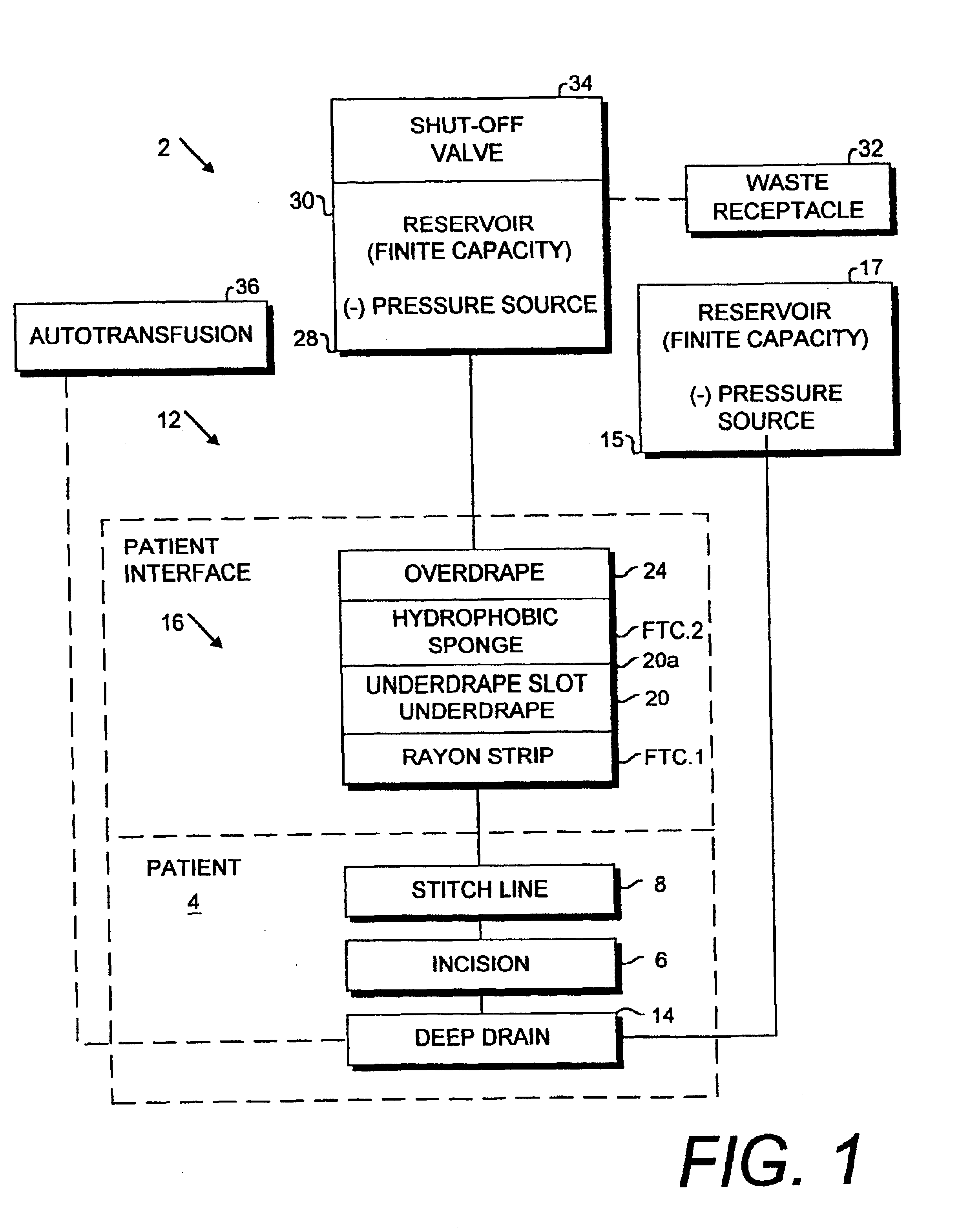
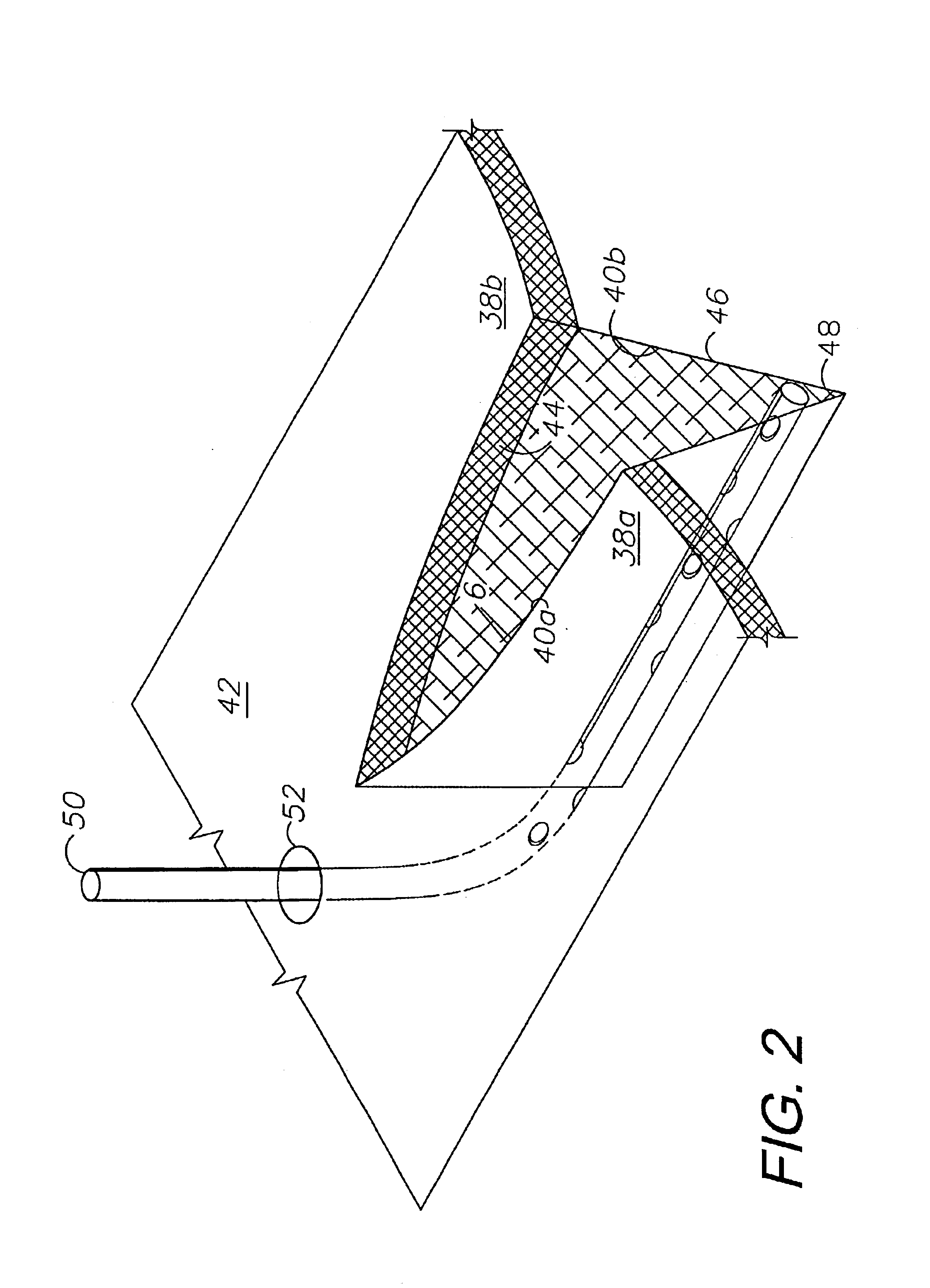
[0015]In the practice of the present invention, a system and method are provided for enhancing closure of separated tissue portions using a surface-applied patient interface. Subsurface drainage, irrigation and autotransfusion components can optionally be used in conjunction with the surface-applied, external interface. The external interface can be advantageously placed over a stitch or staple line and includes a primary transfer component comprising a strip of porous material, such as rayon, applied directly to the patient for wicking or transferring fluid to a secondary transfer component comprising a sponge or foam material. An underdrape is placed between the transfer elements for passing fluid therebetween through an underdrape opening, such as a slot. An overdrape is placed over the secondary transfer component and the surrounding skin surface. The patient interface is connected to a negative pressure source, such as a vacuum assisted closure device, wall suction or a mechanical suction pump. A manual control embodiment utilizes a finite capacity fluid reservoir with a shut-off valve for discontinuing drainage when a predetermined amount of fluid is collected. An automatic control embodiment utilizes a microprocessor, which is adapted for programming to respond to various inputs in controlling the operation of the negative pressure source. A closed wound or incision treatment method of the present invention involves three phases of fluid control activity, which correspond to different stages of the healing process. In a first phase active drainage is handled. In a second phase components can be independently or sequentially disengaged. In a third phase the secondary transfer component can optionally be left in place for protection and to aid in evacuating any residual fluid from the suture / staple line through the primary transfer component.

Problems solved by technology

Tissue separations can result from surgical procedures and other causes, such as traumatic and chronic wounds.
Dead space problems are more apt to occur in the subcutaneous closure.
However, deeper incisions may well require not only skin surface closure, but also time-consuming placement of multiple layers of sutures in the load-bearing planes.
The resulting tissue separations are often subjected to flexure and movement associated with the articulation of the replacement joints.
Although the joints can be immobilized as a treatment option, atrophy and stiffness tend to set in and prolong the rehabilitation period.
For example, arthrotomy, reconstructive and cosmetic procedures, including flaps and scar revisions, also require tissue closures and are often subjected to movement and stretching.
The demands of mobilizing the extremity and the entire patient conflict with the restrictions of currently available methods of external compression and tissue stabilization.

Method used


Image

  • Tissue closure treatment system and method with externally-applied patient interface
  • Tissue closure treatment system and method with externally-applied patient interface
  • Tissue closure treatment system and method with externally-applied patient interface

Examples


Embodiment Construction

I. Introduction and Environment

[0037]As required, detailed embodiments of the present invention are disclosed herein; however, it is to be understood that the disclosed embodiments are merely exemplary of the invention, which may be embodied in various forms. Therefore, specific structural and functional details disclosed herein are not to be interpreted as limiting, but merely as a basis for the claims and as a representative basis for teaching one skilled in the art to variously employ the present invention in virtually any appropriately detailed structure.

II. Tissue Closure System 2

[0038]Referring to the drawings in more detail, the reference numeral 2 generally designates a tissue closure treatment system embodying the present invention. As shown in FIG. 1, the system 2 is adapted for use on a patient 4 with an incision or wound 6, which can be closed by a stitch line 8 consisting of sutures 10, staples or other suitable medical fasteners.

[0039]A patient interface 12 consists of...


PUM


Abstract

A tissue closure treatment system and method are provided with an external patient interface. A first fluid transfer component FTC.1 comprises a strip of porous material, such as rayon, with liquid wicking properties. FTC.1 can be placed directly on a suture line for transferring fluid exuded therethrough. An underdrape is placed over FTC.1 and includes a slot exposing a portion of same. FTC.2 comprises a suitable hydrophobic foam material, such as polyurethane ether, and is placed over the underdrape slot in communication with FTC.1. Negative pressure is applied to FTC.2 through a connecting fluid transfer component FTC.3. A negative pressure source can comprises a manual device or a power-operated suction device. The tissue closure method includes a manual operating mode using a manual suction device with an automatic shut off for discontinuing suction when a predetermined volume of fluid has been drained. An automatic operating mode utilizes a microprocessor, which can be preprogrammed to respond to various patient and operating conditions. The method proceeds through several phases with different components in place and different patient interface functions occurring in each.

Description

BACKGROUND OF THE INVENTION[0001]1. Field of the Invention[0002]The present invention relates generally to medical devices and methods for treating closed wounds and incisions, and in particular to a system and method for draining and / or irrigating tissue separations, such as surgical incisions, and for compressing and stabilizing a dissected or traumatized field with ambient air pressure created by an external patient interface component and a vacuum source.[0003]2. Description of the Related Art[0004]Tissue separations can result from surgical procedures and other causes, such as traumatic and chronic wounds. Various medical procedures are employed to close tissue separations. An important consideration relates to securing separate tissue portions together in order to promote closure and healing. Incisions and wounds can be closed with sutures, staples and other medical closure devices. The “first intention” (primary intention healing) in surgery is to “close” the incision. For lo...

Claims


Application Information

Patent Timeline
Patent Type & Authority Patents(United States)
IPC IPC(8): A61M1/00
CPCA61M1/0088A61M1/0031A61M2205/50A61M2205/3334A61M1/74A61M1/915A61M1/92A61M1/916
Inventor BUBB, STEPHEN K.ZAMIEROWSKI, DAVID S.
Owner 3M INNOVATIVE PROPERTIES CO
Learn More