
Manufacturing method of a snap fastener

a manufacturing method and snap technology, applied in the field of snap fasteners with tape, can solve the problems of complicated molding conditions and complicated molding conditions to prevent an influence of the flow of resin, and achieve the effect of smooth engagement with and detached, reducing the width of the peripheral edge of the attachment hole, and reducing the size of the resilient deformation of the engaging portion

Inactive Publication Date: 2005-10-04
YKK CORP
View PDF13 Cites 4 Cited by
  • Summary
  • Abstract
  • Description
  • Claims
  • Application Information

AI Technical Summary

Benefits of technology

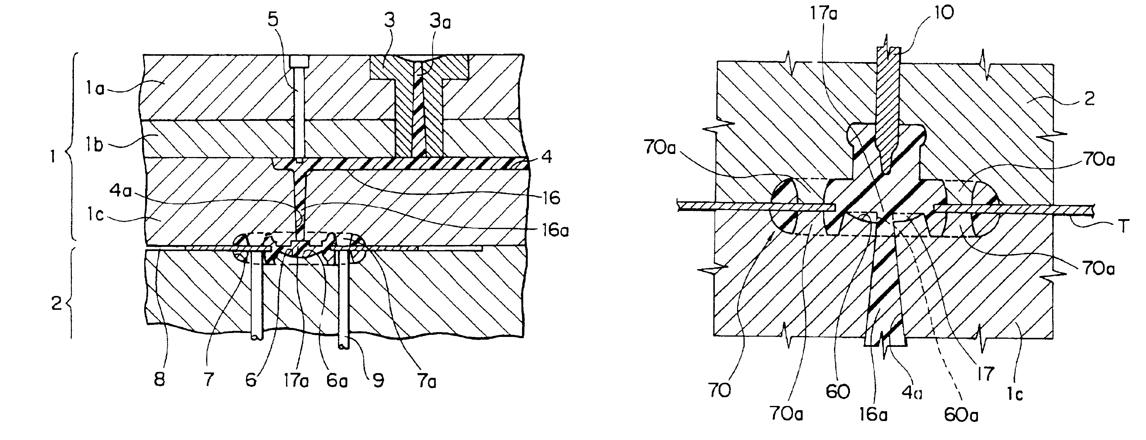
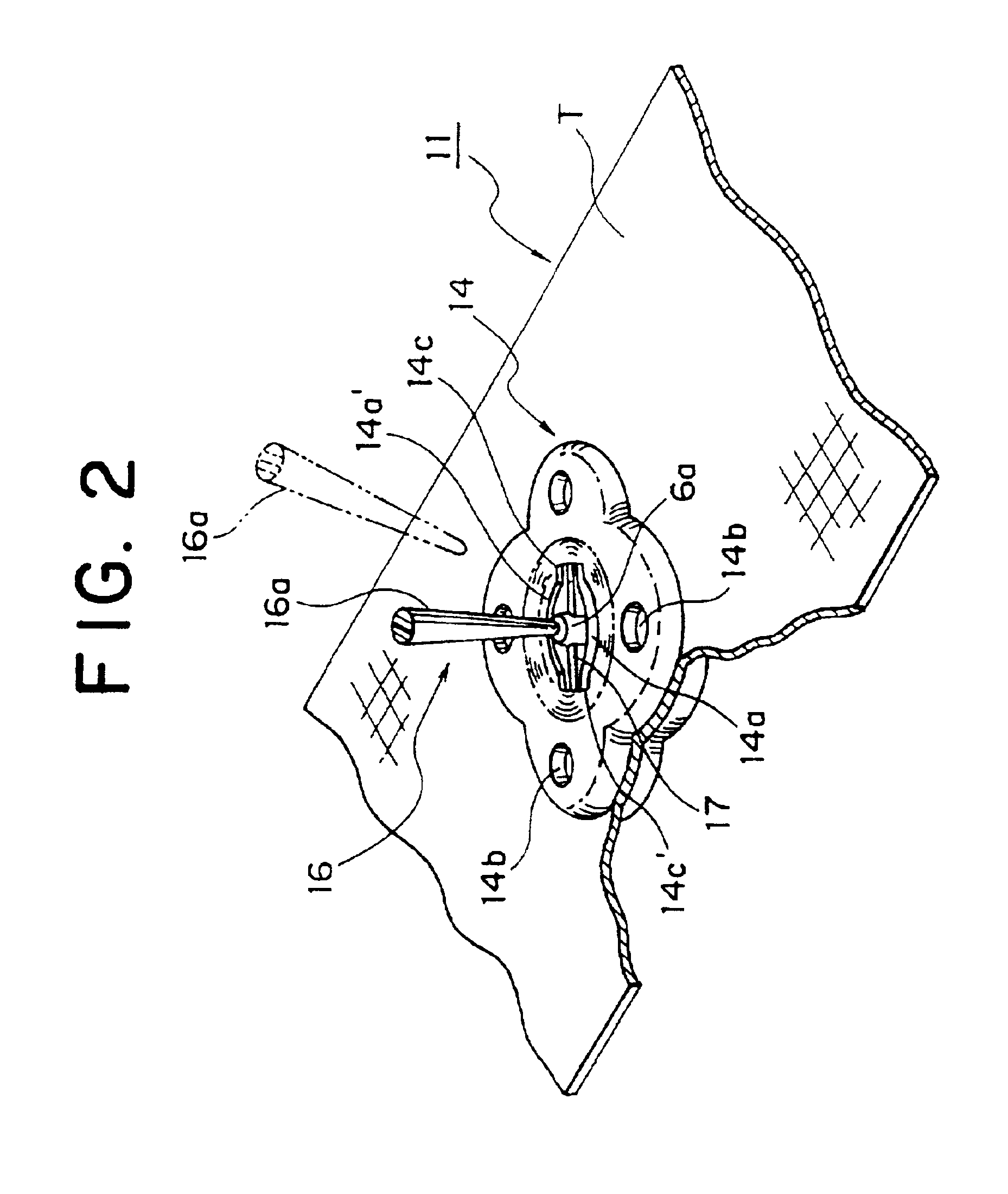
[0015]In this aspect of this invention, a strength of securing of the female button to the tape increases because a proper degree of waving of the peripheral edge of the attachment hole of the tape can be obtained, similarly to the above U.S. patent. Further, because the cut-out is formed at a portion of the inner peripheral engaging face of the engaging opening, a gate in the molding can be formed at the bottom face of the cut-out. Also, the molded gate can be easily fractured and removed by a pushing force generated when the engaging portion of the male button is engaged with the inner peripheral engaging face of the engaging opening. Because the gate burr is formed on the bottom face of the cut-out, there is no problem in appearance of the button, and the female button can be smoothly engaged and disengaged with the male button because the gate burr is formed on an inner side of the inner peripheral engaging face.
[0018]In this aspect, by making the recess deeper than that of conventional art, a thickness of the substrate of the male button can be thinner than that of conventional art, an amount of resin to be used can be decreased. Further, a strength of the substrate can be reinforced by the wedge-shaped projecting rib.
[0020]Further preferably, the projecting streak may be disposed substantially on a straight line connecting a center of the projecting portion and a center of the mold hole. As a result, because the resin flowing on the front and back faces of the tape is directed to the portions clamped by the support members where deformation of the peripheral edge of the attachment hole of the tape is the smallest at the first stage in the molding, the waving of the peripheral edge of the attachment hole can be further decreased.
[0021]It is further preferable that the engaging portion has at least one split groove, and the split groove has an arc-shaped face at a bottom portion of the split groove and stepped plane faces facing each other and having two or more steps with a distance between the stepped plane faces increasing from the arc-shaped face toward an tip end of the engaging head. With this shape of the split groove, it is possible to make the shape of the molded engaging portion to approximate a shape of the cavity without being affected by sink in the molding, and a size of a resilient deformation of the engaging portion is increased, thereby enabling the male member to be smoothly engaged with and detached from the female member.
[0024]In this aspect of the invention, a proper degree of waving of the peripheral edge of the attachment hole of the tape can be obtained to increase a strength of securing of the female button to the tape, similarly to the above U.S. patent as described above. Further, because the cut-out is formed at the portion of the inner peripheral engaging face of the engaging opening, the gate in the molding can be formed on the bottom face of the cut-out. Also, the molded product of the gate can be easily fractured and removed by a pushing force generated when the engaging portion of the male button is engaged with the inner peripheral engaging face of the engaging opening of the female button. Because the gate burr is formed on the bottom face of the cut-out, there is no problem in appearance, and the male button can be smoothly engaged with the female button because the gate burr is formed on an inner side of the inner peripheral engaging face.
[0026]Further, according to the second aspect of the invention, there is provided a manufacturing method wherein the snap fastener is a female member comprising the female button which has an engaging opening at a center portion of the female button and which is integrally molded on the tape, and the method further includes the steps of forming the molten resin outlet portion of the one or more molten resin guide passage to project and open inside the cavity, forming the respective molten resin guide passage independently, and fracturing and removing a molded portion of the molten resin guide passage connected to a bottom portion of the cut-out formed by the molten resin outlet portion(s) in a diameter direction of the female button in a portion of an inner peripheral engaging face of the engaging opening, by engaging the engaging portion of the male button with the engaging opening of the female button. Therefore, the female member can be stably manufactured.

Problems solved by technology

Because of this structure, the molds are complicated and the resin flows from one face of the tape to the other face.
Thus, a setting of molding conditions for preventing an influence of the flowing of the resin is complicated.

Method used


Image

  • Manufacturing method of a snap fastener
  • Manufacturing method of a snap fastener
  • Manufacturing method of a snap fastener

Examples


Embodiment Construction

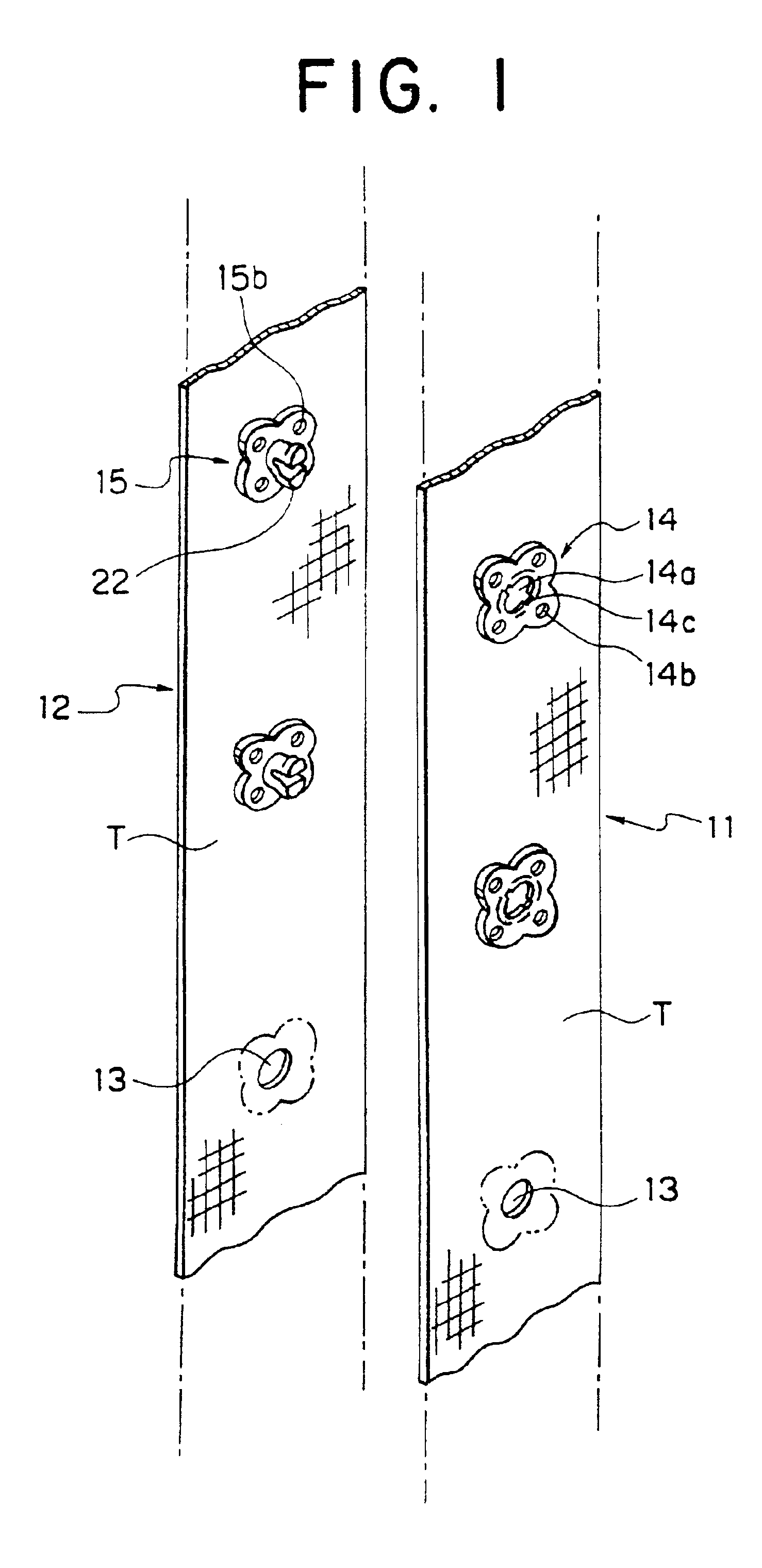
[0044]Preferred embodiments of a snap fastener with tape according to the present invention, and a manufacturing method and a mold of the snap fastener will be described in detail below by reference to the accompanying drawings. FIG. 1 is a perspective view of a portion of male and female members disposed side by side and constituting the snap fastener with tape according to the invention, the members being integrally molded on the tape.

[0045]As shown in FIG. 1, the snap fastener with tape of the invention comprises the female member 11 and the male member 12, and a basic principle of the method for manufacturing the members 11 and 12 follows the manufacturing method disclosed in the above U.S. Pat. No. 2,821,764. In other words, a plurality of attachment holes 13 are formed in a long tape T at predetermined intervals. Then the tape T is supplied into a mold. Thereafter, a female button 14 and a male button 15 are integrally molded on front and back faces of the tape T so as to hold...


PUM

PropertyMeasurementUnit
diameteraaaaaaaaaa
shapeaaaaaaaaaa
pressureaaaaaaaaaa

Abstract

A female member of a snap fastener with tape comprising a female button made of synthetic resin which is integrally molded on front and back faces of the tape so as to hold a peripheral edge of an attachment hole of the tape having at least one attachment hole and which has an engaging opening to be engaged with a male button at a substantially center portion of the female button. The female button has at least one mold hole extending in a front and back direction of the tape, and at least one portion of the tape extends to an inside of the female button across the mold hole. At least one cut-out recessed in a diameter direction of the female button is defined in a portion of an inner peripheral engaging face of the engaging opening, and a gate burr is formed at a bottom face of the cut-out. Therefore, in the snap button with tape, and a manufacturing method and a mold of the snap button, in spite of a mold with a simple structure having a small number of pairs of pin members, gate burrs are not exposed on a surface, and the snap button can be easily manufactured without a special step for removing the gates, and the button can be firmly secured to the tape.

Description

[0001]This is a continuation of application Ser. No. 09 / 404,900, filed Sep. 24, 1999, now abandoned which is a divisional of application Ser. No. 09 / 266,129, filed Mar. 10, 1999, now U.S. Pat. No. 6,079,083, all of which are incorporated herein by reference.BACKGROUND OF THE INVENTION[0002]1. Field of the Invention[0003]The present invention relates to a snap fastener with tape, which is made of synthetic resin, and a manufacturing method and a mold of the snap fastener.[0004]2. Description of the Related Art[0005]It has been known for a long time to form at least one attachment hole in a single tape, and integrally mold an eyelet or a similar article made of synthetic resin with a desired shape onto front and back faces of the tape such that the eyelet or the article holds a peripheral edge of the attachment hole. As disclosed in U.S. Pat. No. 2,821,764, for example, an attachment hole is formed in a sheet material, and an eyelet made of synthetic resin with a desired shape is inte...

Claims


Application Information

Patent Timeline
Patent Type & Authority Patents(United States)
IPC IPC(8): A44B17/00B29C45/14
CPCA44B17/0035A44B17/0047A44B17/0052A44B17/0058B29C45/14344Y10T24/45932Y10T24/45775Y10T24/3683Y10T24/45937A44D2201/50A44B17/00A44B19/00
Inventor AKASHI, SHUNJI
Owner YKK CORP
Learn More