Conductive fabric with balanced mutual interference amongst conductors

Inactive Publication Date: 2005-10-04
NORMAN RICHARD S
View PDF4 Cites 6 Cited by
  • Summary
  • Abstract
  • Description
  • Claims
  • Application Information

AI Technical Summary

Problems solved by technology

One effect that takes place during analog or digital signal transmission is mutual interference amongst the wires of the bus.
As a result of mutual interference, the signal travelling along a given individual wire of the bus will become corrupted.
Such an effect may be even more pronounced due to signal degradation resulting from the distance travelled by the signal from its source, in addition to the mutual interference effect.
Of course, a signal that arrives in a state where it is either below the noise floor or corrupted under the strong influence of the signal in a neighbouring channel will cause a degradation in the performance of the circuit as a whole.
However, although this pattern is simple to achieve in the case of flexible cables by a mere twisting motion, it is extremely prohibitive to attain in the case of printed circuit boards and even more so for an integrated circuit.
In fact, it would be impossible to manufacture such a pattern by means of standard lithographic techniques employing layers and vias.

Method used


Image

  • Conductive fabric with balanced mutual interference amongst conductors
  • Conductive fabric with balanced mutual interference amongst conductors
  • Conductive fabric with balanced mutual interference amongst conductors

Examples


Embodiment Construction

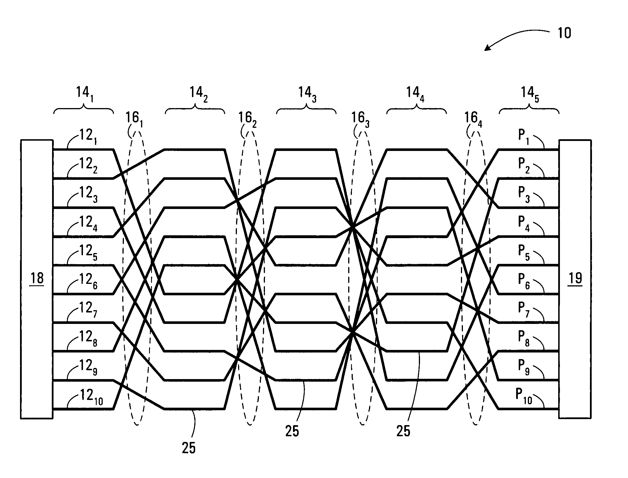
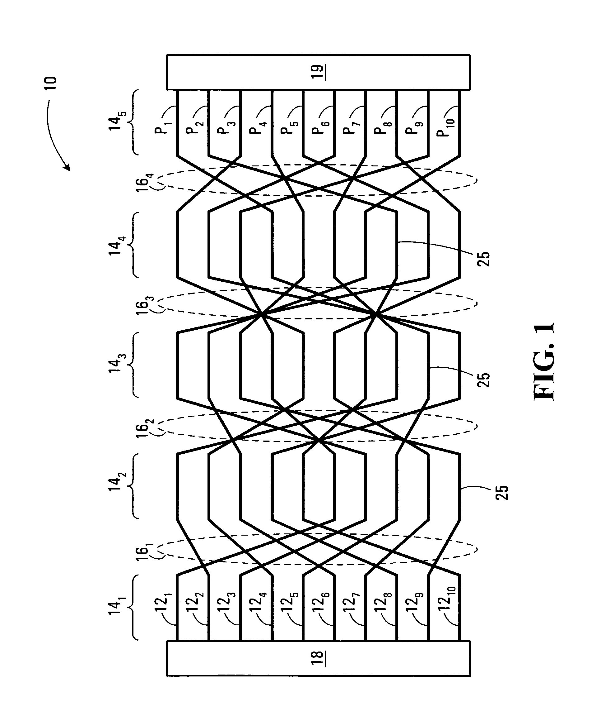
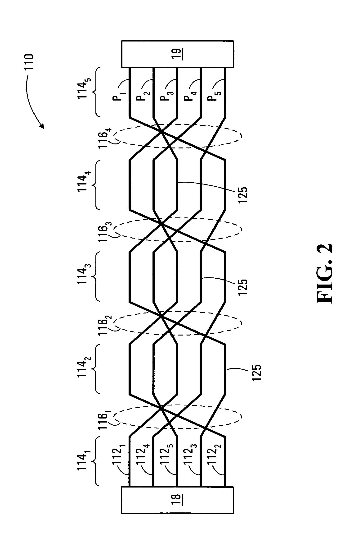
[0022]With reference to FIG. 1, there is shown a conductive fabric 10 in accordance with an embodiment of the present invention. The conductive fabric 10 includes a plurality of conductive elements 121–12N which are arranged in an alternating sequence of segments. 141–14K and cross-over regions 161–16Q. FIG. 1 illustrates a conductive fabric including N=10 conductive elements, K=5 segments and Q=4 cross-over regions. The conductive elements 121–12N may be made of any suitable material, such as copper or aluminum. The conductive elements 121–12N may consist of a combination of signal-carrying conductive elements as well as conductive elements that are kept at a reference potential. The signal-carrying conductive elements 121–12N may carry analog or digital signals in either or both directions of communication across the conductive fabric 10. While not essential, in a specific example of implementation, a first processing element 18 is connected to a first end of the conductive fabric...


PUM


Abstract

A conductive fabric including a plurality of conductive elements defining an alternating sequence of segments and cross-over regions. Within each of the segments, the conductive elements are arranged substantially in parallel; within each of the cross-over regions located between two adjacent segments, the conductive elements are permuted so as to allow the position occupied by at least one of the conductive elements to be different in each of the two adjacent segments. Between a pair of reference segments, each of the conductive elements experience coupling with respect to a subset of said conductive elements other than itself, the coupling experienced by each of the conductive elements being substantially identical.

Description

CROSS-REFERENCES TO RELATED APPLICATIONS[0001]This application claims the benefit of U.S. Provisional Patent Application Ser. No. 60 / 436,628 filed Dec. 30, 2002, hereby incorporated by reference herein.[0002]The present invention is related in subject matter to U.S. Provisional Patent Application Ser. No. 60 / 343,167, filed on Dec. 31, 2001, hereby incorporated by reference herein.[0003]The present invention is also related in subject matter to U.S. patent application Ser. No. 10 / 330,230, filed on Dec. 10, 2002, hereby incorporated by reference herein.FIELD OF THE INVENTION[0004]The present invention pertains to electrical conductors in general and, more specifically, to laying out multiple conductors on a printed circuit board or in an integrated circuit where the conductors are closely spaced to one another.BACKGROUND OF THE INVENTION[0005]It is frequently the case that plural, closely spaced electrical conductors are used to join various elements of a circuit. For example, it is c...

Claims


Application Information

Patent Timeline
IPC IPC(8): H01B11/00H05K1/02
CPCH05K1/0228H05K2201/09245H05K2201/09263
Inventor NORMAN, RICHARD S.
Owner NORMAN RICHARD S
Why Eureka
Try Eureka