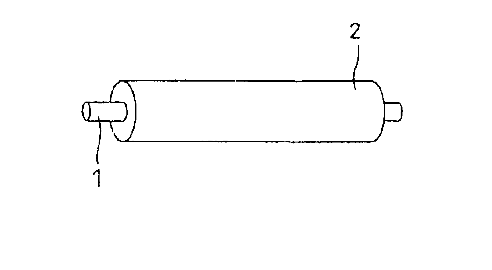
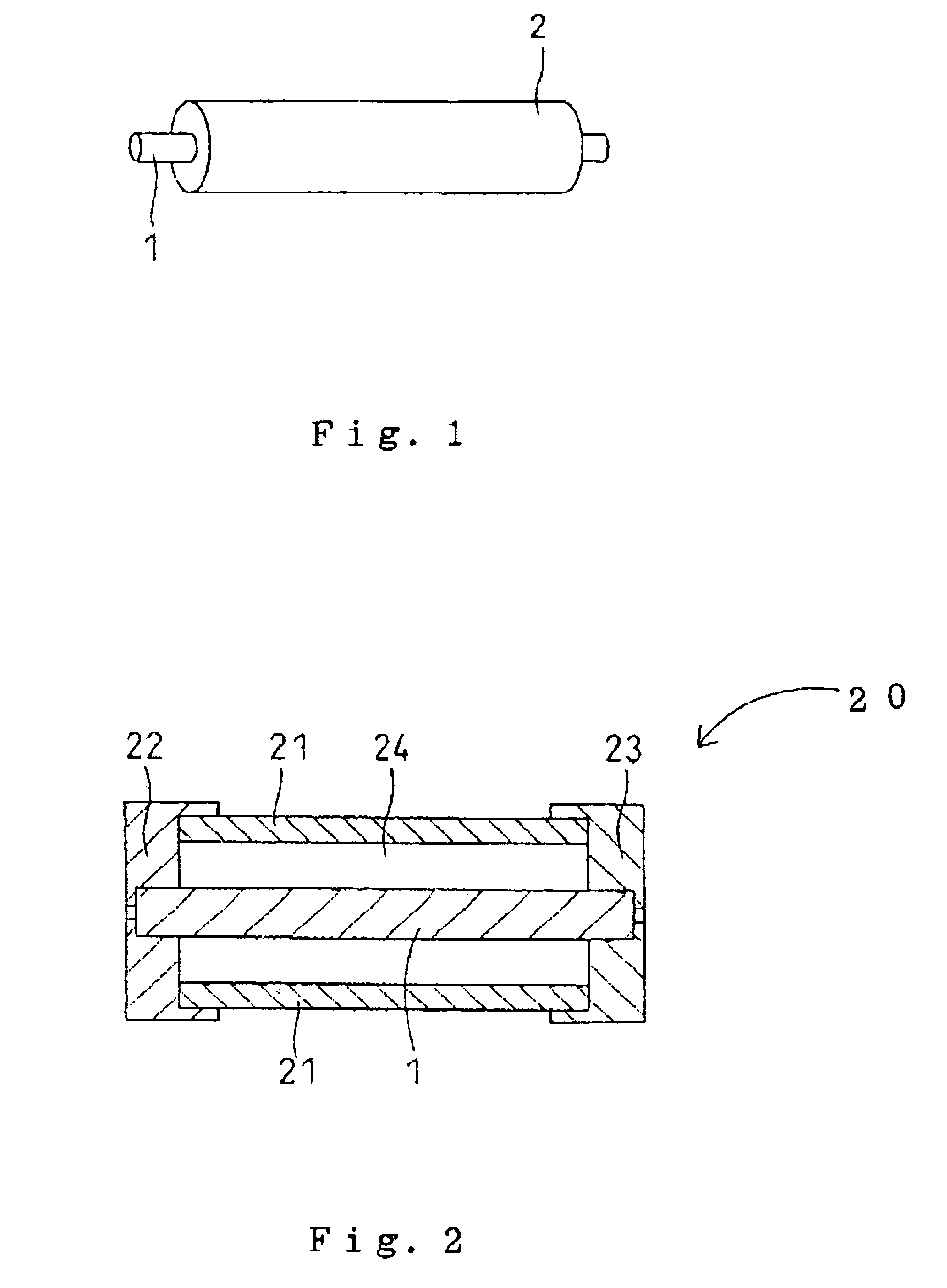
Toner supply roll

Active Publication Date: 2005-10-04
TOKAI RUBBER IND LTD
View PDF18 Cites 8 Cited by
  • Summary
  • Abstract
  • Description
  • Claims
  • Application Information

AI Technical Summary

Benefits of technology

[0010]In view of the fact that the conventional evaluation methods involving measurements of the dimensions and the hardness of the toner supply roll fail to properly and accurately evaluate a toner supply roll for possible imaging failure in the formation of a copy image or the like, the inventors of the present invention conducted intensive studies to find an additional property requirement for a toner supply roll to help predict possible imaging failure. The inventors investigated the cause of the imaging failure associated with the toner supply roll, and found that a toner supply roll fails to uniformly supply a toner onto a developer roll if the outermost urethane foam layer thereof has a low shape recovery rate. O

Problems solved by technology

However, a toner supply roll judged to have little numerical variation in dimensions and in hardness by the aforesaid evaluation methods is often determined to be inferior and unacceptable when actually used for image formation.
That is, i

Method used


Image

  • Toner supply roll
  • Toner supply roll
  • Toner supply roll

Examples


example 1

[0046]A urethane material was prepared by mixing the ingredients in proportions as shown in Table 1, and a toner supply roll was produced in the manner described above with reference to FIG. 2. More specifically, a mold as shown in FIG. 2 was first prepared, and a metal core shaft 1 (having a diameter of 5 mm and composed of SUS304) was placed within a cylinder 21 of the mold. A premixed polyol was prepared by blending the polyol, the electrically conductive agent, the curing catalyst, the foaming agent and the foam stabilizer in a ratio as shown in Table 1, and then mixed with the isocyanate in a predetermined ratio. A suitable amount of the resulting mixture was injected into the cavity 24 of the mold, and heated in an oven at 60° C. for 30 minutes to thereby foam and cure the mixture. Thereafter, the resulting product was unmolded. Thus, a toner supply roll of a single layer structure was produced, which the roll including a urethane foam layer (having a thickness of 4 mm) provid...


PUM


Abstract

A toner supply roll free from occurrence of an imaging failure. The toner supply roll comprises a shaft (1) and a urethane foam layer (2) provided on an outer peripheral surface of the shaft (1), wherein when the urethane foam layer is compressed to a depth of 1 mm from an outermost surface thereof during compression thereof to a depth of 2 mm, a stress F0 occurs in the urethane foam layer and when the urethane foam layer is decompressed to a depth of 1 mm after the compression thereof to a depth of 2 mm, a stress F1 occurs in the urethane foam layer, the urethane foam layer satisfies a relation represented by the following expression (1) at a temperature of 23±3° C. at a humidity of 50±10%:
F1/F0≧0.7  (1)
the stresses F1 and F0 being expressed by a unit of Pa.

Description

BACKGROUND OF THE INVENTION[0001]1. Field of the Invention[0002]The present invention relates to a toner supply roll for use in an electrophotographic apparatus such as a copying machine, a printer or a facsimile machine.[0003]2. Description of the Art[0004]In an image forming apparatus such as a copying machine, a printer or a facsimile machine, an image forming operation is performed, as shown in FIG. 3, by forming an electrostatic latent image of an original image on a surface of a photoreceptor drum 12, causing a toner to adhere on the electrostatic latent image to form a toner image, transferring the toner image onto a sheet, and fixing the toner image on the sheet. For the formation of the toner image, a predetermined toner (developer) is supplied onto a surface of a developer roll 17 from a toner box (not shown) by a toner supply roll 11, and then transferred onto the surface of the photoreceptor drum 12 from the surface of the developer roll 17. The thickness of a layer of t...

Claims


Application Information

Patent Timeline
IPC IPC(8): F16C13/00G03G15/08
CPCG03G15/0808G03G2215/0634
Inventor OHKUWA, KENICHIYASUI, EIJITOYAMA, KAZUNORI
Owner TOKAI RUBBER IND LTD
Why Eureka
Try Eureka