
Method for protecting a security module and arrangement for the implementation of the method

Inactive Publication Date: 2005-10-04
FRANCOTYP POSTALIA
View PDF32 Cites 11 Cited by
  • Summary
  • Abstract
  • Description
  • Claims
  • Application Information

AI Technical Summary

Benefits of technology

[0013]An object of the present invention is to assure protection against a security module being tampered with, requiring little outlay when the security module is replaceably mounted. The replacement should be possible in optimally simple way.
[0015]The invention proceeds on the basis of identifying the replacement and use of a security module of a postage meter machine, mail-processing means or similar device with function units in order to be able to offer the users of the various devices assurance regarding the correct functioning of the security module, and thus of the overall device. Replacement of a security module is detected and a status is subsequently signaled when the security module is re-plugged and supplied with a system voltage. Modifications in the status of the security module are acquired with a first function unit and with a detection unit supplied by a battery, which has a self-holding capability that can be reset. The first function unit can interpret the respective condition when it is re-supplied with system voltage. The advantages are a fast reaction to modifications of the status of the security module and low battery power consumption of the circuit of the detection unit while the security module is not being supplied with the system voltage.

Problems solved by technology

Repair of a postage meter machine is possible only with difficulty on site where the access to the components is rendered more difficult or limited.
This means that a reduction of the voltage below a specific limit value leads to an undesired behavior of the component: the RTC stands still and the time of day—stored in SRAM cells—and the memory contents of the SRAM are preserved.
At least one of the security measures, for example long time watchdogs, would then be ineffective at the side of the postage meter machine.
However, the service life of the non-replaceable battery, and thus of the security module, is too short for use in franking devices or mail-processing machines.
The power consumption increases due to the use of a number of sensors, and a security module not constantly supplied by a system voltage then draws the current required for the sensors from its internal battery, which likewise prematurely drains the battery.
The capacity of the battery and the power consumption thus limit the service life of a security module.
Since extreme care is required in the replacement of an assembly that contains security-relevant data, the replacement usually requires a service technician and measures that, given improper use or unauthorized replacement of a security module, suppress the functioning thereof.
Such measures are extremely complicated.

Method used


Image

  • Method for protecting a security module and arrangement for the implementation of the method
  • Method for protecting a security module and arrangement for the implementation of the method
  • Method for protecting a security module and arrangement for the implementation of the method

Examples


Embodiment Construction

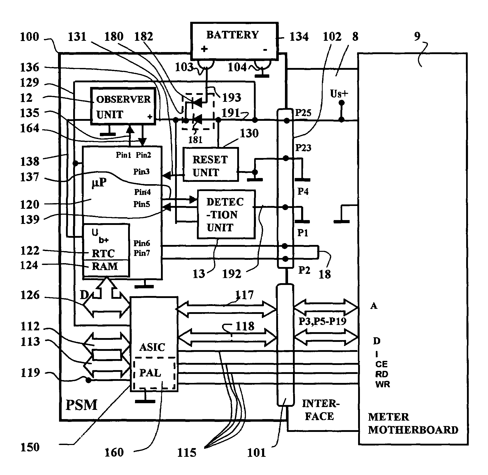
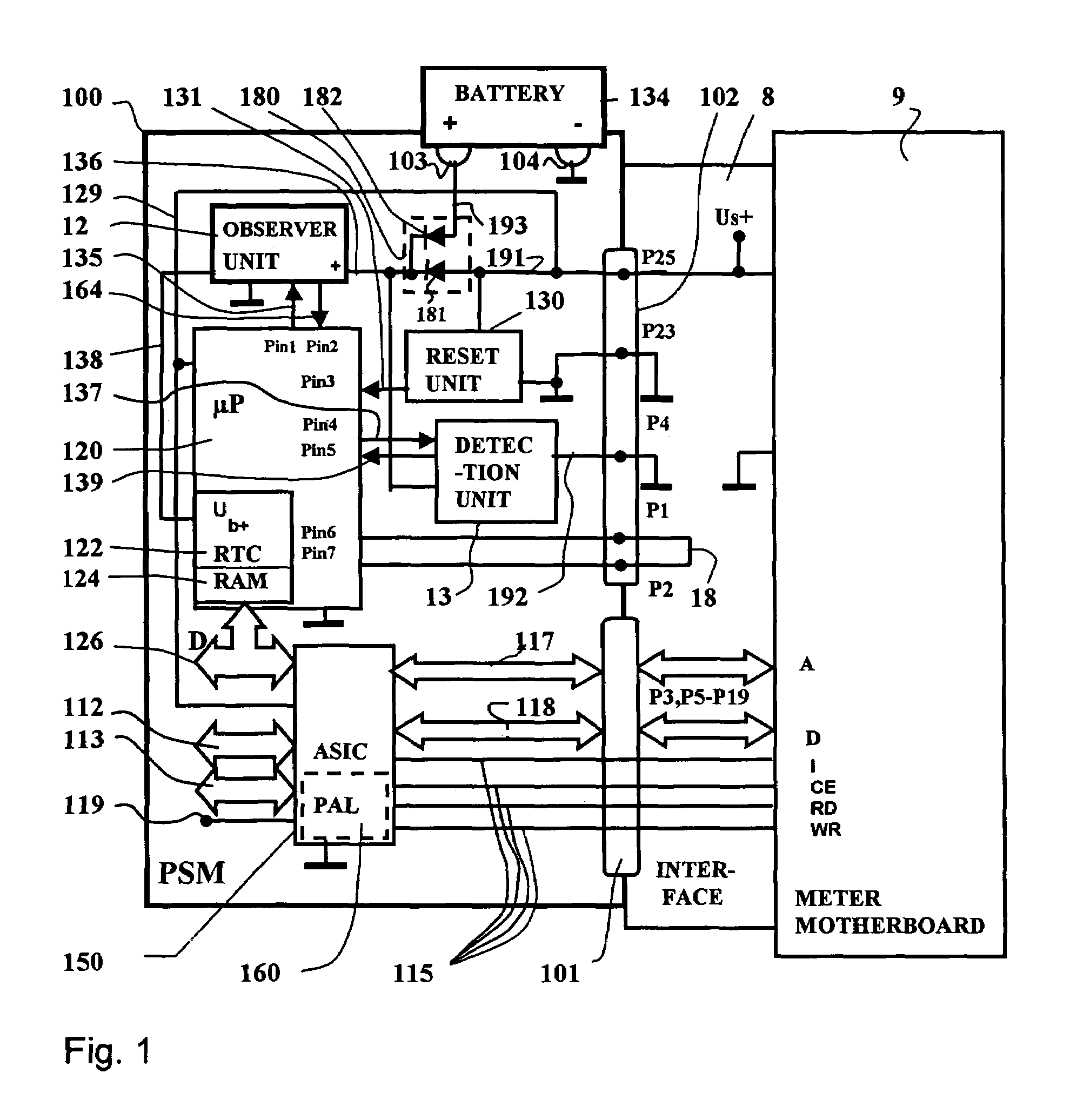
[0027]FIG. 1 shows a block diagram of the security module 100 with the contact groups 101,102 for connection to an interface 8 as well as to the battery contact posts 103 and 104 of a battery interface for a battery 134. Although the security module 100 is potted with a hard casting compound, the battery 134 of the security module 100 is replaceably arranged on a printed circuit board outside the casting compound. The printed circuit board carries the battery contact posts 103 and 104 for the connection of the poles of the battery 134. The security module 100 is plugged to a corresponding interface 8 of the motherboard 9 with the contact groups 101,102. The first contact group 101 has a communicative connection to the system bus of a control unit, and the second contact group 102 serves the purpose of supplying the security module 100 with the system voltage. Address and data lines 117, 118 as well as control lines 115 proceed via the pins P3, P5–P19 of the contact group 101. The fi...


PUM


Abstract

A method for protecting a security module includes the steps of monitoring proper insertion of the module on a device motherboard with first, second and third function units, erasing sensitive data due to an improper use or a replacement of the module with the second function unit, inhibiting the functionality of the module with the third function unit during a replacement of the security module, re-initializing the previously erased, sensitive data following proper use or replacement of the security module, and re-commissioning by enabling the function units of the security module. An arrangement implementation of the method has an unplugged status detection unit that has a circuit for resettable self-holding of a status indicator, the self-holding being triggered when the voltage level on a test voltage line deviates from a predetermined potential. A processor connected to the other function units and is programmed to identify and modify the status of the security module.

Description

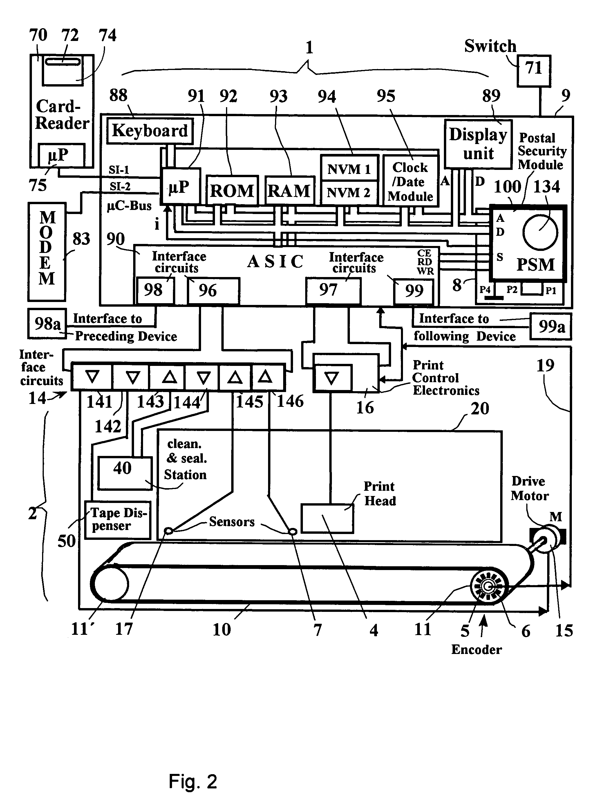
BACKGROUND OF THE INVENTION[0001]1. Field of the Invention[0002]The present invention is directed to a method for protecting a security module to an arrangement for the implementation of the method, particularly a postal security module suitable for use in a postage meter machine or mail-processing machine or a computer with mail-processing capability.[0003]2. Description of the Prior Art[0004]Modern postage meter machines, such as the thermal transfer postage meter machine disclosed in U.S. Pat. No. 4,746,234, utilize a fully electronic, digital printer. It is thus fundamentally possible to print arbitrary texts and special characters in the franking imprint printing field and an advertising slogan that is arbitrary or allocated to a cost center. For example, the postage meter machine T1000 of the Francotyp-Postalia AG & Co. has a microprocessor that is surrounded by a secured housing that has an opening for the delivery of a letter. When a letter is supplied, a mechanical letter s...

Claims


Application Information

Patent Timeline
IPC IPC(8): G07B17/00
CPCG07B17/00733G07B2017/00233G07B2017/00298G07B2017/00306G07B2017/00346G07B2017/00403G07B2017/00967
Inventor POST, PETERROSENAU, DIRKSCHLAAFF, TORSTEN
Owner FRANCOTYP POSTALIA
Learn More