Mounting system

a mounting system and mounting plate technology, applied in the field of mounting plates, can solve the problems of many problems, and the wall coverings, such as sheetrock, drywall, plasterboard, etc., do not provide a secure base to securely attach fixtures, and achieve the effect of reducing deformation and enlarged effective mounting area

Inactive Publication Date: 2005-10-11
REECHCRAFT
View PDF25 Cites 6 Cited by
  • Summary
  • Abstract
  • Description
  • Claims
  • Application Information

AI Technical Summary

Benefits of technology

[0009]The mounting system of the present invention is typically utilized with walls having an inner frame with vertical stud members and a substrate, such as a rigid foam insulation placed between the studs. The studs and insulation are typically covered with a material such as paneling or drywall panels and then painted, wallpapered, etc. The mounting system has mesh backing elements that include pointed tab portions at the corners of the backing elements that are pressed into and engage the substrate. Fixtures may be mounted to the wall covering, and in some instances, the wall covering may be directly mounted to the backing elements. Mounting hardware, such as screws or bolts, ar

Problems solved by technology

Mounting fixtures and other elements to walls is a common job with which many problems may be encountered.
Many wall coverings, such as sheetrock, drywall, plasterboard, paneling and other similar types of wall covering materials, do not provide a secure base to securely attach fixtures.
In addition, such materials often have insulation backing the sheetrock or similar material where the fixture is to be mounted.
Insulation is typically a fiberglass or foam insulation that does not provide a sufficient anchor point for receiving screws, bolts and other fasteners.
Studs for the frame may provide a better solution for mounting, but may be difficult to locate behind a

Method used


Image

  • Mounting system
  • Mounting system
  • Mounting system

Examples


second embodiment

[0025]Referring to FIG. 4, there is shown a mesh backing element 24. The backing element 24 includes planar portions 32 at a right angle to one another forming a corner. Pointed tab portions 30 extend outward from the L-shaped profile for mounting to interior corners of buildings. Such a configuration provides support to difficult to access locations at the peak of the corner and also provides support along the intersection between the two converging sections of wall 100. Greater support is provided, as well as improved, clean appearance.

third embodiment

[0026]Referring now to FIG. 5, there is shown a mesh backing element, generally designated 26. The backing element 26 has a profile similar to backing element 24, but the pointed tabs 30 extend inward from the right angle of planar portions 32 so that the backing element 26 is mountable to exterior corners. The corner backing element 26 aids in bringing the two converging sections of the wall 100 together and retaining them in alignment and in engagement. It will be appreciated that multiple mounting elements may be utilized in a spaced apart arrangement to retain the underlying substrate 102 and provide a clean, finished corner and receiving the outer layer 104.

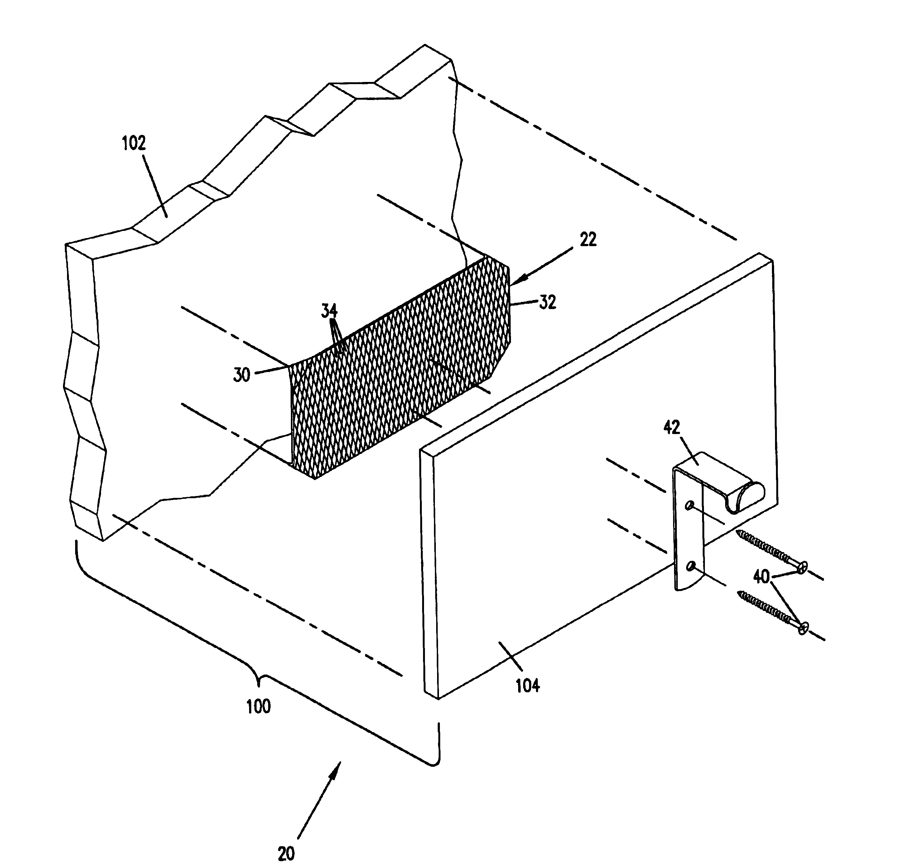
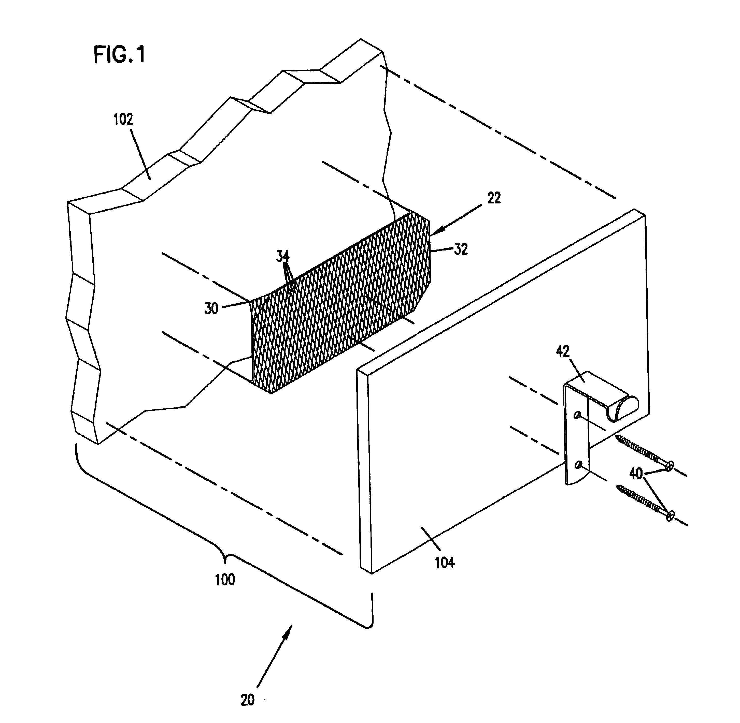
[0027]In one embodiment, the mesh backing elements 22, 24 and 26 having a diamond shaped mesh pattern. A typical preferred application utilizes a mesh of 18 gauge cold rolled steel in a ⅛ inch flattened expanded pattern. Typical mesh openings 34 have a length of 0.133 inches and a width of 0.056 inches. However, other dimens...


PUM


Abstract

A wall mounting system includes an interlocking mesh backing element mounting to a substrate, such as foam insulation. The backing element has pointed corner portions that are pushed into the substrate and retain the backing element. A wall covering layer such as drywall overlays the substrate and the mesh backing element. A fixture having has bolts, screws or other attachment members extending through the wall covering layer and the mesh backing element. The system has several backing element styles, including planar elements, inner right angle elements and outer right angle elements.

Description

[0001]This application hereby claims benefit of priority under Title 35, United States Code § 119(e) of U.S. provisional application Ser. No. 60 / 305,306 filed Jul. 13, 2001 and is incorporated herein by reference.BACKGROUND OF THE INVENTION[0002]1. Field of the Invention[0003]The present invention relates to a mounting system for building walls, and in particular to a mounting system utilizing interlocking mesh backing elements.[0004]2. Description of the Prior Art[0005]Mounting fixtures and other elements to walls is a common job with which many problems may be encountered. Many wall coverings, such as sheetrock, drywall, plasterboard, paneling and other similar types of wall covering materials, do not provide a secure base to securely attach fixtures. In addition, such materials often have insulation backing the sheetrock or similar material where the fixture is to be mounted. Insulation is typically a fiberglass or foam insulation that does not provide a sufficient anchor point f...

Claims


Application Information

Patent Timeline
IPC IPC(8): E04F13/08E04F19/02E04F19/00E04B1/38E04F19/04
CPCE04B1/7637E04F11/1804E04F19/0495E04B2001/386E04F19/02E04F19/04
Inventor NICKEL, SHANE L.
Owner REECHCRAFT
Why Eureka
Try Eureka