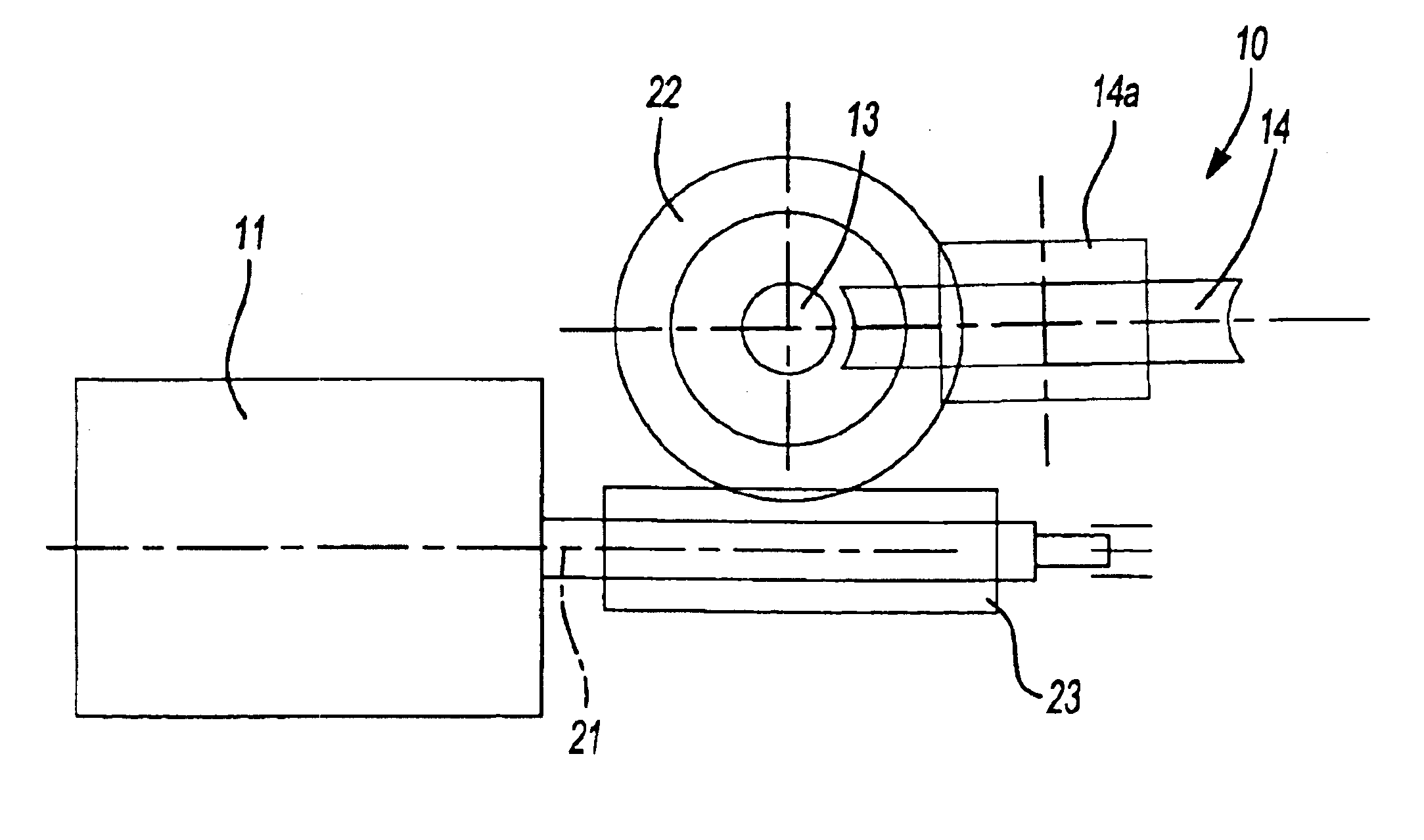
[0005]Since here the drive system is designed so that the worm gear is the output member, a pivot angle of 360° in both rotational directions may be achieved since the worm gear is completely free to rotate. The worm gear may be connected directly to the pivoting component or, on the other hand, through appropriate linking elements. The preferred approach is to provide the worm gear with a shaped hole to create the positive-fit connection to an input-side component such as a pin of a device which is adjustable by the drive system. This provides a form-fit connection which prevents any displacement over time of the
connected component relative to the worm gear. Preferred shapes of the shaped hole include that of a multiple spline or polygon. A square hole is preferred, however. This design has the
advantage that the worm gear of the drive system may be slid onto an appropriately shaped pin of the adjustable device. The drive system is appropriately located in a two-part housing so that after
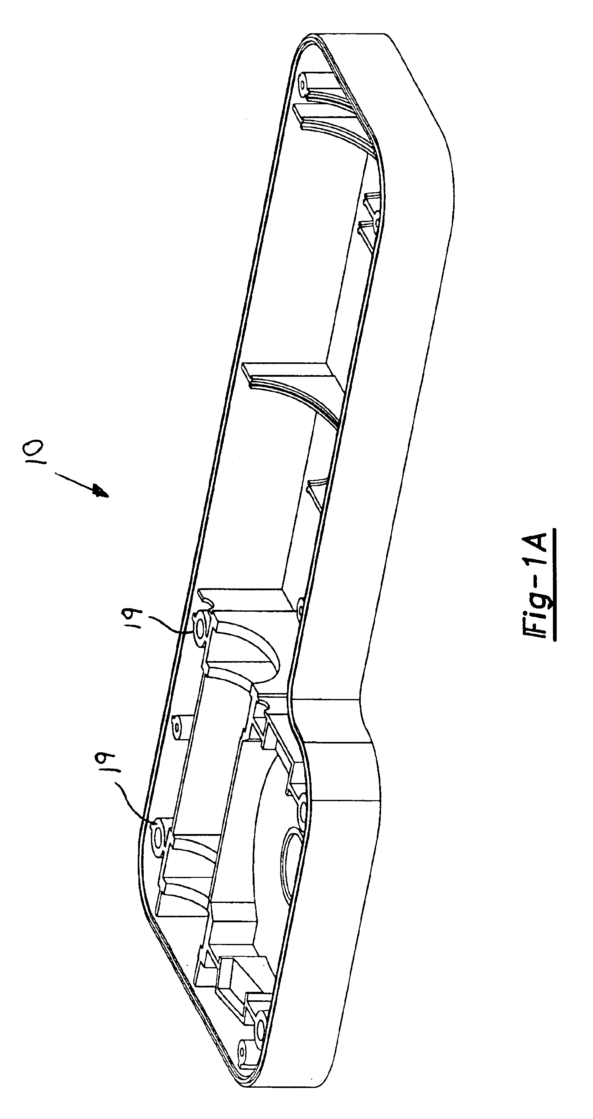
assembly, the second housing component may be connected to the first housing component, for example by a screw-on connection. The housing components are designed to be permanently attached in the simplest manner to the object, for example, the frame 30 of an armchair.
[0006]The drive system in question should be not only compact, and thus of a space-saving design, but also inexpensive to produce. The approach used is therefore one in which the worm engaging the worm gear is designed as a threaded spindle, a trapezoidal threaded spindle being a preferred design. These spindles are available commercially, and are thus extremely inexpensive. Since the drive system is in
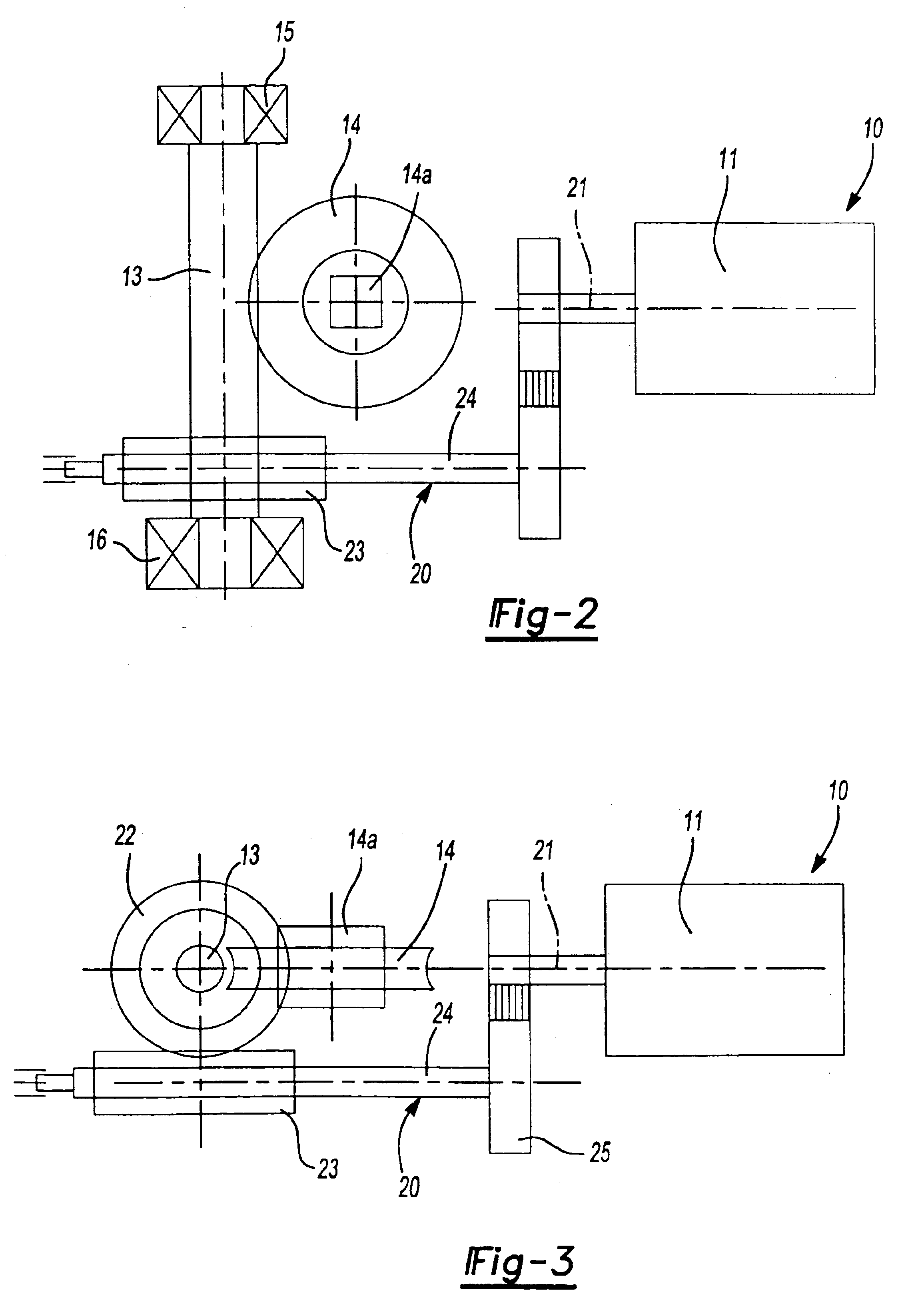
continuous operation, this design of the worm and worm gear is completely adequate. In most usage situations, the rotational angle of the worm gear must be restricted. This angle is based on the adjustment range of the driven device. Provision is thus made to limit the rotational angle of the worm gear by appropriately positioned limit switches. These limit switches may also be adjustable, thus allowing the rotational angle to be adjusted for the specific use. An especially preferred design has the worm gear coupled to a radial
cam, the latter being designed so that the
limit switch or limit switches may be actuated in accordance with the function. The radial
cam may be rotatable relative to the worm gear such that the rotational angle of the worm gear may be increased or decreased by rotating the radial
cam. It is also possible, however, to provide the worm gear with pins for example, which strike fixed stops, thereby raising the level of the current supplied to the motor, as a result of which this rise is measurable, and the motor is switched off by an appropriate
signal. The rotational speed of the worm gear should be extremely low. This property may be achieved by modifying the size or the number of teeth; however, since the drive system in question should have the smallest dimensions possible, a further modification interposes a gear unit which reduces the input rotational speed between the worm and the drive motor. This gear unit, or these gear units, significantly reduce the rotational speed of the worm relative to the output pin of the drive motor. It is especially advantageous if each interposed gear unit is an epicyclic gear unit, preferably a planetary gear unit. These gear units are not only of compact design, but their ratio of input speed to output speed of the drive motor is especially high. Each gear unit should be designed, however, so that the associated output pin is oriented in the direction of the output pin of the drive motor. It is especially advantageous if the output pin of each gear unit is aligned with the output pin of the drive motor since this configuration facilitates a compact design. In a preferred design, the drive motor is a
DC motor operating on a safety isolating
voltage of 24 volts or 42 volts.
[0009]In another embodiment, the drive system is not dependent on the rotational angles of the limit switches and stops limiting the output worm gear - with the result that the output worm gear may be rotated without restriction, that is, it may complete more than one full revolution. It is especially advantageous if the housing of the
electric drive system may be provided with two openings which are opposite one another as well as aligned with the shaped hole in the output worm gear so that one of the openings selectively faces a mechanism adjustable by the drive system. The installation position of the
electric drive system is then selectable. A torque arm is appropriately provided on the housing of the drive system to maintain the position of the drive system during operation. This torque arm is appropriately a bracket containing a hole, the bracket being molded onto the housing and located opposite the output end, thereby creating the largest possible lever arm. Since the drive system can be operated in multiple installation positions, it is appropriate to have two spaced brackets, each containing a hole, molded onto the housing. This arrangement accordingly creates a fork head.
[0010]In another embodiment, a first worm gear is mounted in a rotationally fixed manner onto the output pin of the drive motor, the worm gear engaging a worm, and the output worm gear including the shaped hole is directly or indirectly drivable by an additional worm gear. In this design, the epicyclic gear after the drive motor is normally dispensed with. It is especially advantageous if the drive motor is fixed by a form-fit connection within three supports, this design eliminating the need for any additional attachment elements. In a preferred design, these supports may, however, consist of screws which engage corresponding recesses or pockets. It is also possible to provide the drive motor at its end face opposite the output pin with a central lug which engages one of the supports.
[0011]In another design, it is possible to attach the drive motor by screws to the housing of the drive system, preferably on the side facing the output pin, and to make the screws of a
noise-attenuating material, for example, a plastic, or to make the screws of
metal and have the screw heads which engage notched recesses surrounded, either completely or partially, by a nonmetallic material. Each attenuating ring might be made, for example, of plastic or rubber. If rubber is used, the attenuating rings could be standard O-rings. The use of plastic screws or the use of attenuating rings reduces overall
noise created by operation of the drive system. If the drive motor is attached by supports within the housing, a design might be used in which, preferably, the supports associated with the drive side of the drive motor 11 are offset in such a manner that, with a form-fit attachment of the drive motor, compressive and / or tensile forces may act on the motor housing. The drive motor is accordingly braced such that the connection remains intact even in response to extremely long use. Attachment of the drive motor to the housing may also be accomplished by an end plate which is preferably mounted on the end face facing the output pin. This end plate appropriately has at least two attachment holes allowing for screw attachment to the housing. The attachment plate may be advantageously designed as a molded part which has pins in its edge regions, or the overall
edge region is raised. In addition, it is possible for the
rotational axis of the drive motor to be in an oblique orientation relative to the wall of the housing. This configuration, for example, allows a favorable
pressure angle to be created for the drive component mounted on the output pin relative to another component.

