Offshore platform stabilizing strakes

a technology of stabilizing strakes and offshore platforms, which is applied in the direction of special-purpose vessels, vessel construction, transportation and packaging, etc., can solve the problems of reducing the stability of the spar platform, the control of the trim and stability, and the relative complexity of the management, so as to reduce or eliminate the effect of vortex-induced vibrations

Active Publication Date: 2005-10-11
DEEPWATER TECH
View PDF6 Cites 54 Cited by
  • Summary
  • Abstract
  • Description
  • Claims
  • Application Information

AI Technical Summary

Benefits of technology

[0012]In accordance with the present invention, an improved apparatus is provided for reducing or eliminating vortex-induced vibrations resulting from water currents acting on the hull of a floating platform of a type that includes an elongated, submerged, annular hull, that is used for offshore oil and gas drilling and production operations. In an exemplary embodiment, the apparatus includes one or more modular, helical strakes, each comprising a plurality of generally rectangular segments or modules that extend substantially radially outward from the hull, and that are arranged in a spaced-apart, end-to-end relationship that defines a discontinuous, generally helical band extending around a substantial portion of the lower circumference of the hull.

Problems solved by technology

For example, because of their elongated, slender shape, they can be relatively more complex to manage during offshore operations under some conditions than other types of platforms in terms of control over their trim and stability.
In particular, because of their elongated, slender shape, spar platforms are particularly susceptible to vortex-induced vibrations (“VIV”) resulting from strong currents acting on the hull of the platform.
While such prior art efforts at reducing or eliminating VIV of spar hulls do address the problem to some extent, they are also either relatively complex, and hence, expensive to implement, or heavy and difficult to assemble and incorporate into the hull efficiently.

Method used


Image

  • Offshore platform stabilizing strakes
  • Offshore platform stabilizing strakes
  • Offshore platform stabilizing strakes

Examples


Embodiment Construction

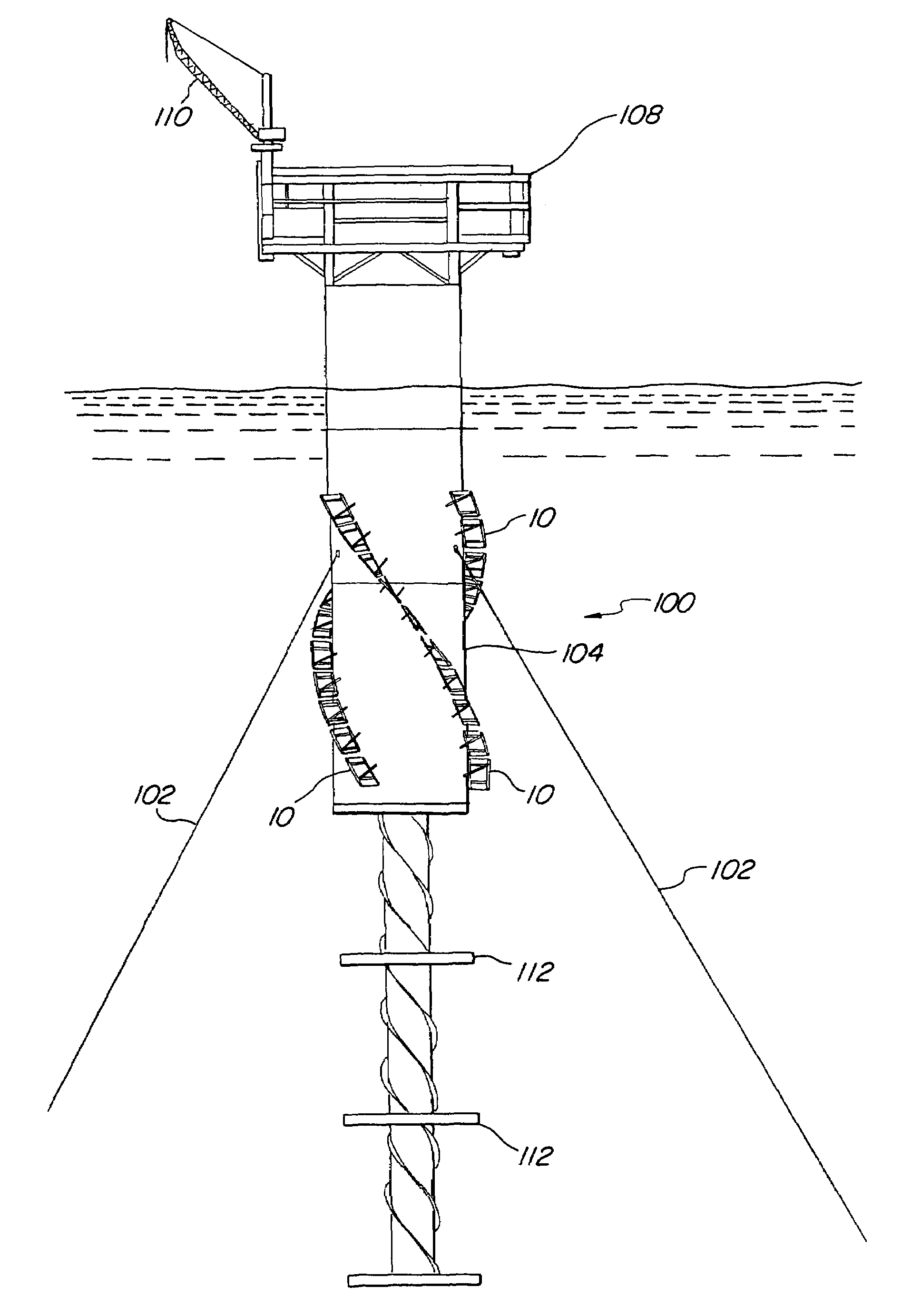
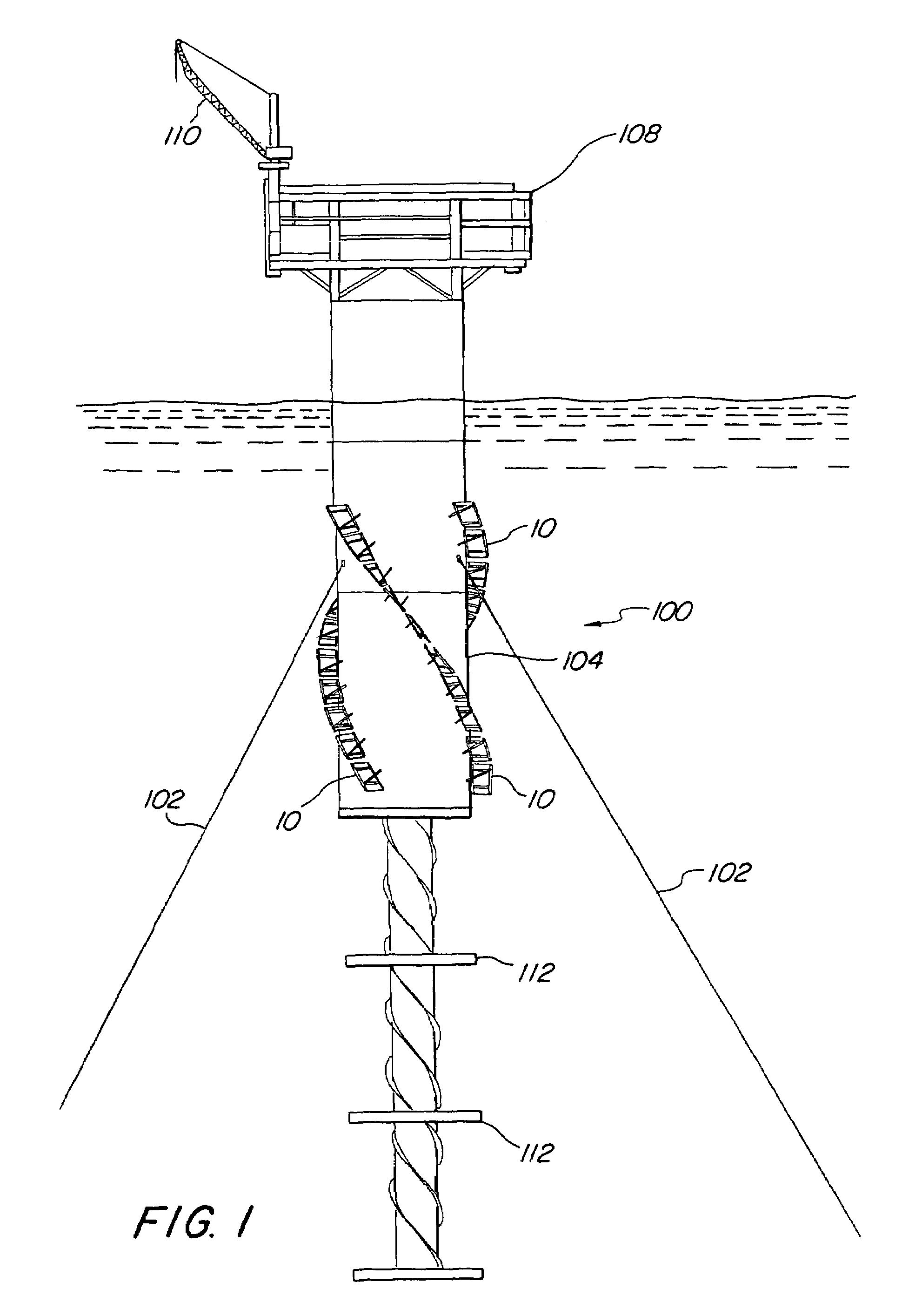
[0025]An elevation view of an exemplary, spar-type offshore oil and gas drilling and production platform 100 incorporating an exemplary embodiment of segmented, helical stabilizing strakes 10 in accordance with the present invention is illustrated in FIG. 1, in which the platform is shown floating upright in a deep body of water and anchored to the seafloor (not illustrated) by a plurality of mooring lines 102. As illustrated, the exemplary spar platform comprises a single annular hull 104 having a lower portion submerged below the surface 106 of the water to a selected depth, which in one possible embodiment, may be as deep as about 500 ft. (152 m) or more, and an upper portion extending above the surface of the water to a selected height, which may be as high as 50 ft. (15 m) or greater. The particular exemplary hull illustrated may have a diameter ranging from 50 to 170 ft. (15 to 51 m), weigh between 8,000 and 30,000 tons (7,256–27,210 MT), and optionally, be capable of storing ...


PUM


Abstract

An elongated, annular hull of a floating offshore platform includes one or more segmented, helical strakes disposed on an outer peripheral surface of the hull to reduce vortex-induced vibrations resulting from water currents. The hull may comprise a single annular hull or a plurality of parallel, adjacent hulls. Each strake includes a plurality of generally rectangular segments extending substantially radially outward from the hull. Each of the segments includes a pair of spaced-apart radial stanchions supporting a generally rectangular frame to which a corresponding panel is attached. The panels have a radial width that is about 13 percent of the effective diameter of the hull. The segments are arranged in a spaced-apart, end-to-end relationship that defines a discontinuous, but generally helical band extending around the circumference of the hull from about 35 feet (11.7 m) below the mean water line of the hull to its lowermost end.

Description

CROSS-REFERENCE TO RELATED APPLICATIONS[0001](Not Applicable)FEDERALLY SPONSORED RESEARCH OR DEVELOPMENT[0002](Not Applicable)BACKGROUND OF THE INVENTION[0003]1. Field of the Invention[0004]This invention relates to oil and gas drilling and production equipment in general, and in particular, to an improved form of helical strakes which are useful for stabilizing floating, deep water offshore oil and gas drilling and production platforms.[0005]2. Description of Related Art[0006]Offshore oil and gas drilling and production operations involve the provision of a vessel, or platform, sometimes called a “rig,” on which the drilling, production and storage equipment, together with the living quarters of the personnel manning the platform, if any, are mounted. In general, offshore platforms fall into one of two classes, viz., “fixed” and “floating” platforms.[0007]Fixed platforms comprise an equipment deck supported by legs that are seated directly or indirectly on the sea floor. While rela...

Claims


Application Information

Patent Timeline
Patent Type & Authority Patents(United States)
IPC IPC(8): B63B39/00B63B35/44B63B21/00B63B21/50B63B1/04
CPCB63B35/44B63B39/005B63B1/048B63B2021/504B63B2035/442B63B2039/067E21B15/02B63B39/00B63B21/50
Inventor HORTON, EDWARD E.
Owner DEEPWATER TECH
Why Eureka
Try Eureka