Contrast medium delivery system and associated method

a delivery system and contrast medium technology, applied in the field of devices and systems for delivering contrast medium to patients, can solve the problems of introducing room air into the co/sub>delivery system, posing a great danger to patients, affecting the patient's health, etc., and preventing the inadvertent introduction of excessive amounts of contrast medium into the patient, preventing the explosion of gaseous contrast medium (carbon dioxide) into the patient, and preventing accidental infusion of contrast medium

Inactive Publication Date: 2005-10-11
ANGIODYNAMICS INC
View PDF11 Cites 55 Cited by
  • Summary
  • Abstract
  • Description
  • Claims
  • Application Information

AI Technical Summary

Benefits of technology

[0009]Another object of the present invention is to provide such a device or system wherein air can be effectively eliminated prior to the feeding of the contrast medium to the patient.
[0021]In a device or system in accordance with the present invention for delivering contrast medium to a patient's vascular system, air can be effectively eliminated prior to the feeding of the contrast medium to the patient. Highly pressurized sources of contrast medium are isolated from the patient, thereby preventing inadvertent introduction of excessive amounts of contrast medium into the patient. Also, explosive introduction of gaseous contrast medium (carbon dioxide) into the patient can be minimized or eliminated.

Problems solved by technology

Air and CO2 are invisible so introduction of air into a CO2 delivery system would pose a danger to a patient if it were inadvertently injected into the vasculature.
But since CO2 is invisible introduction of room air into the system would pose a great danger to the patient.
The air would go undetected and, once in the patient's vasculature, could cause a blockage or even an air embolism to the brain resulting in a stroke or death.
The problem with this method is that the CO2 cylinder pressure is much higher than blood pressure (830 psi vs.

Method used


Image

  • Contrast medium delivery system and associated method
  • Contrast medium delivery system and associated method
  • Contrast medium delivery system and associated method

Examples


Embodiment Construction

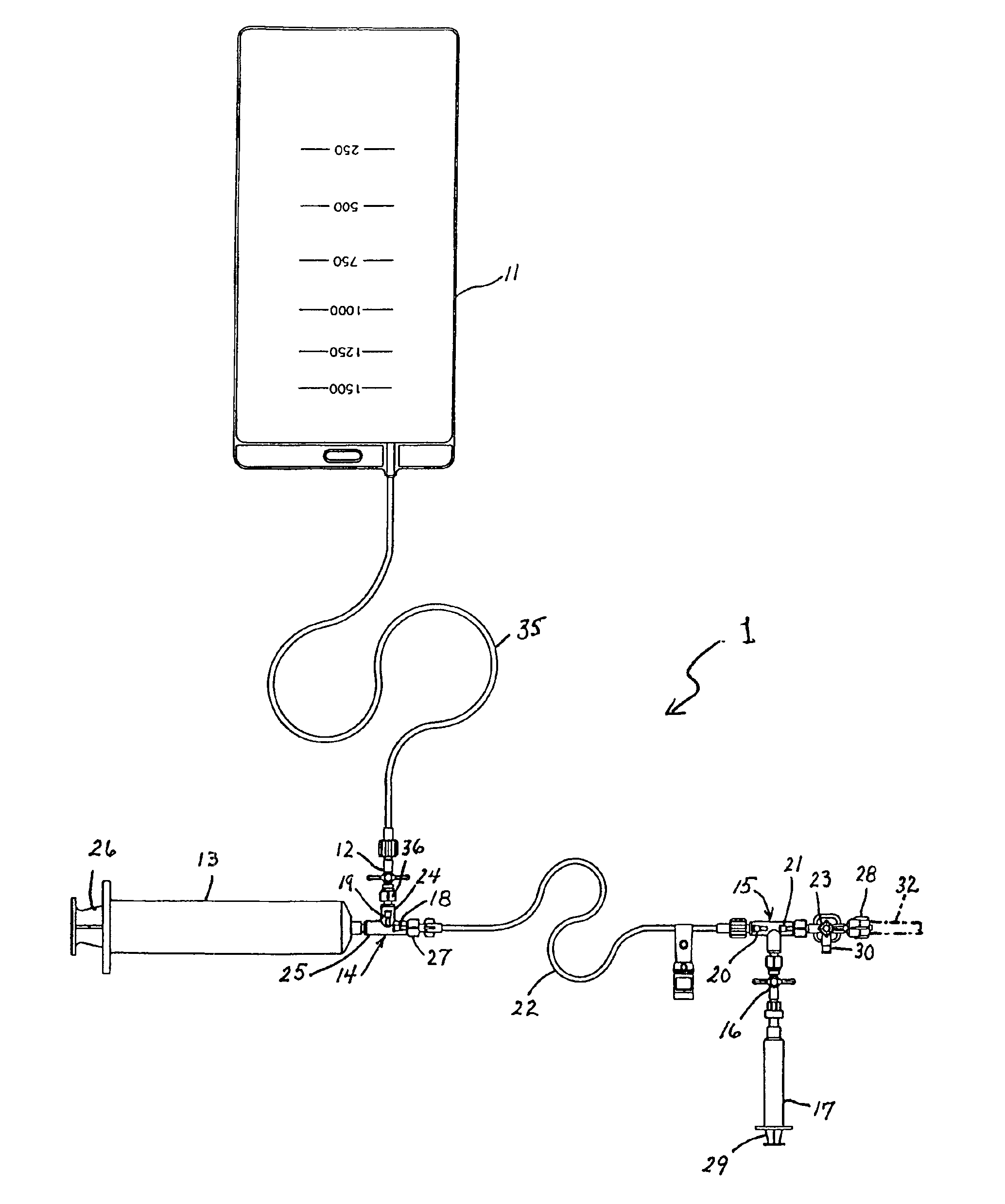
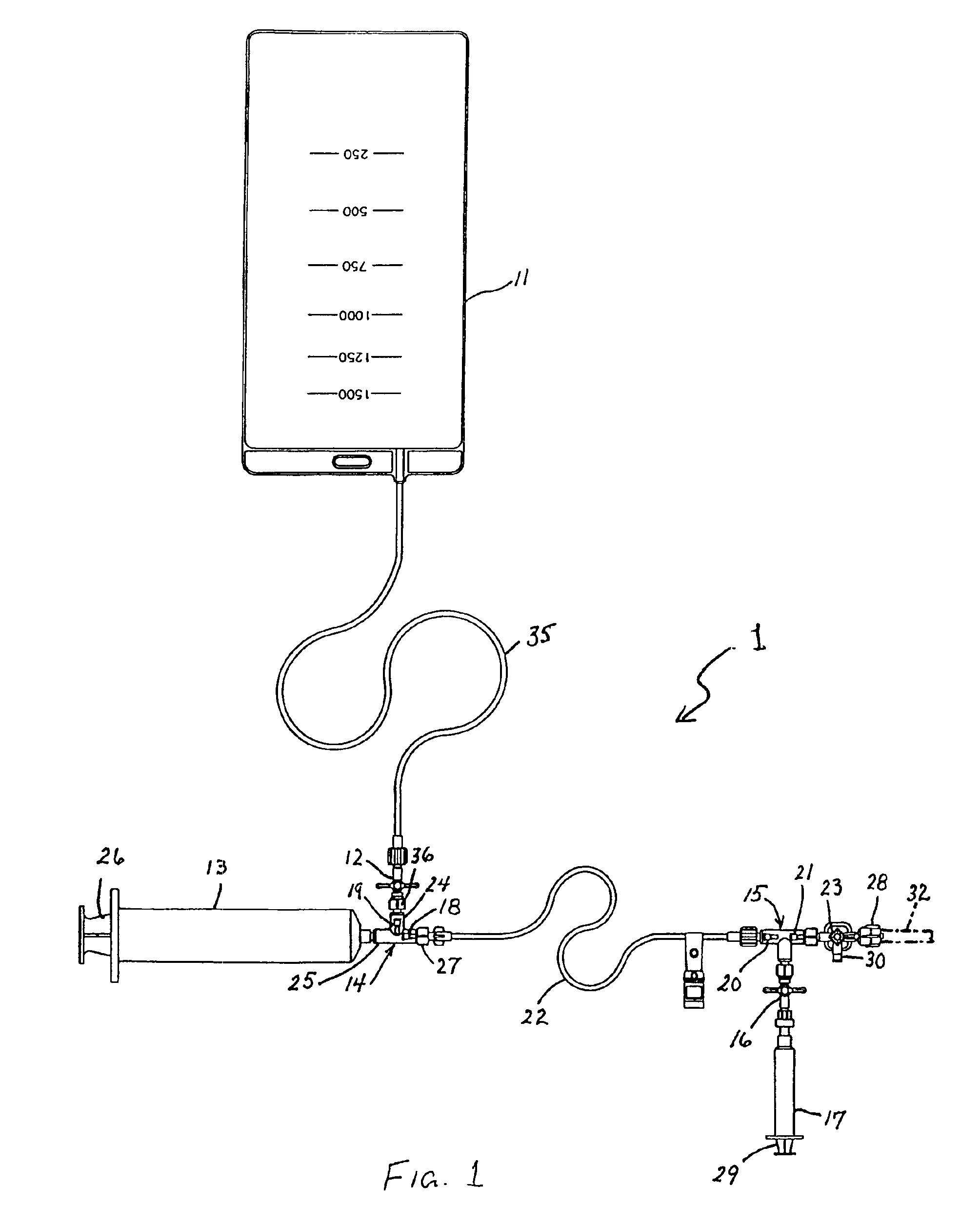
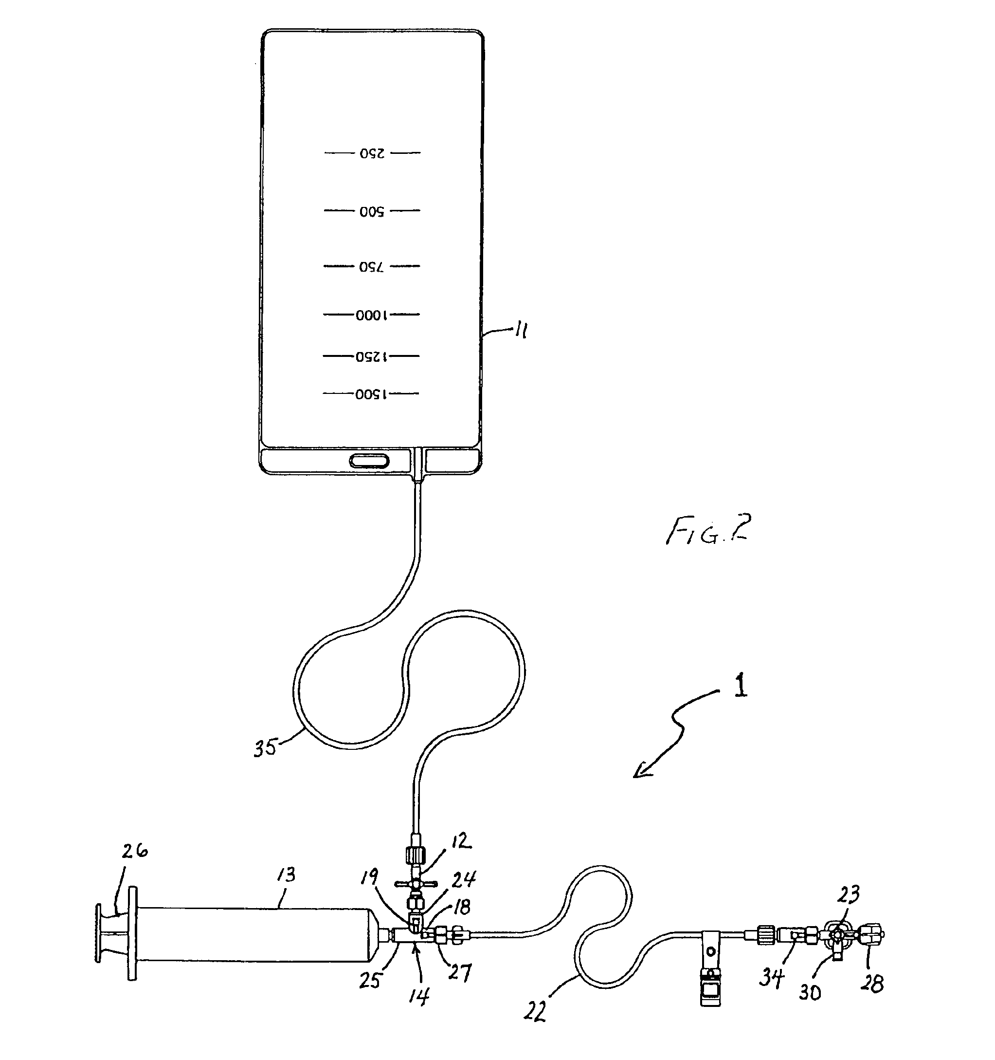
[0024]As illustrated in FIG. 1, a system 1 for controllably infusing carbon dioxide contrast medium into a patient's vasculature comprises a flexible reservoir bag 11, a one-way reservoir bag stopcock 12, a delivery syringe 13, a dual check valve 14, an in-line check valve 15, a distal one-way stopcock 16, a purge syringe 17, a connecting tube 22, and a patient stopcock 23. This system 1 will remove the high-pressure CO2 cylinder from the vicinity of the patient and maintain a closed system that reduce or eliminate the chance introduction of air into the patient's vasculature.

[0025]Reservoir bag 11 is made of a soft elastomeric, non-porous material. When bag 11 is filled to its capacity or just under capacity (500-2000 ml), the bag is at ambient atmospheric pressure. Therefore, bag 11 will not have a tendency to deliver CO2 gas into the patient even if the bag is coupled directly to the patient's vasculature. The patient's blood pressure will be higher than the pressure of the bag. ...


PUM


Abstract

A device cooperating with a pump for guiding a contrast medium from a source thereof to a catheter for delivery to a patient's vascular system. The device comprises a dual check valve, a tubular member, an in-line check valve and a three-port stopcock. The dual check valve has an inlet port connectable to the source of contrast medium, an inlet-outlet port connectable to the pump, and an outlet port coupled to the tubular member. The in-line check valve is connected to the tubular member at a point spaced from the dual check valve for preventing fluid flow towards the dual check valve. The stopcock connected at a first port to the in-line check valve, a second port of the stopcock being operatively connectable to the catheter. Using this device, medical personnel infuses contrast medium into the patient from the source without having to disconnect any element from the device during the infusion process.

Description

CROSS-REFERENCE TO A RELATED APPLICATION[0001]This is a Divisional of application Ser. No. 08 / 966,671, filed Nov. 10, 1997 now U.S. Pat. No. 6,315,762 which in turn claims the priority of Provisional Application Ser. No. 60 / 031,116, filed Nov. 14, 1996.BACKGROUND OF THE INVENTION[0002]This invention relates to a device and a system for delivering contrast medium to a patient. The device and system are especially effective for delivering carbon dioxide gas to the vascular system of a patient. This invention also relates to an associated method for delivering contrast medium such as carbon dioxide gas to a patient.[0003]Delivery systems for contrast media have been used for many years in the medical field. Keeping the system a “closed system” so that no room air will be introduced is critical to the features of these delivery systems. With the advent of carbon dioxide gas or CO2 as a viable fluid for displacing blood in vessels for visualization under Digital Subtraction Angiography (...

Claims


Application Information

Patent Timeline
Patent Type & Authority Patents(United States)
IPC IPC(8): A61M5/00
CPCA61M5/007
Inventor RECINELLA, DANIEL K.HOBBS, EAMONN
Owner ANGIODYNAMICS INC
Why Eureka
Try Eureka