Emergency communication system

a communication system and emergency communication technology, applied in the field of emergency communication systems, can solve problems such as the inability to start a vehicl

Inactive Publication Date: 2005-10-11
PANASONIC CORP
View PDF12 Cites 13 Cited by
  • Summary
  • Abstract
  • Description
  • Claims
  • Application Information

AI Technical Summary

Benefits of technology

[0005]It is another object of the present invention to provide an emergency communication system, in which, when the removable type emergency communication conveying means as described above is detached or removed from the emergency communication system terminal unit, it is possible to reliably connect the conveying means, i.e. the handy phone, by notifying the user of such detachment.
[0046]According to still another aspect of the present invention, there is provided an emergency communication system of the above basic aspect of the invention, wherein, when a handy phone used as the emergency communication conveying means is removed from the emergency communication system terminal unit, a status information indicating that the emergency communication conveying means has been removed is outputted to the information transmitting means such as buzzer, LED, etc. for transmitting information to the user. Based on the status information, the information transmitting means transmits the information that the emergency communication conveying means has been removed to the user by means such as sound, illumination, display, etc., and reliable operation of the emergency communication conveying means is maintained while the vehicle is being driven.

Problems solved by technology

Also, it is designed in such manner that, if the emergency communication conveying means is not connected normally or if it is not operated, the vehicle cannot be started.

Method used


Image

  • Emergency communication system
  • Emergency communication system
  • Emergency communication system

Examples


embodiment 1

(Embodiment 1)

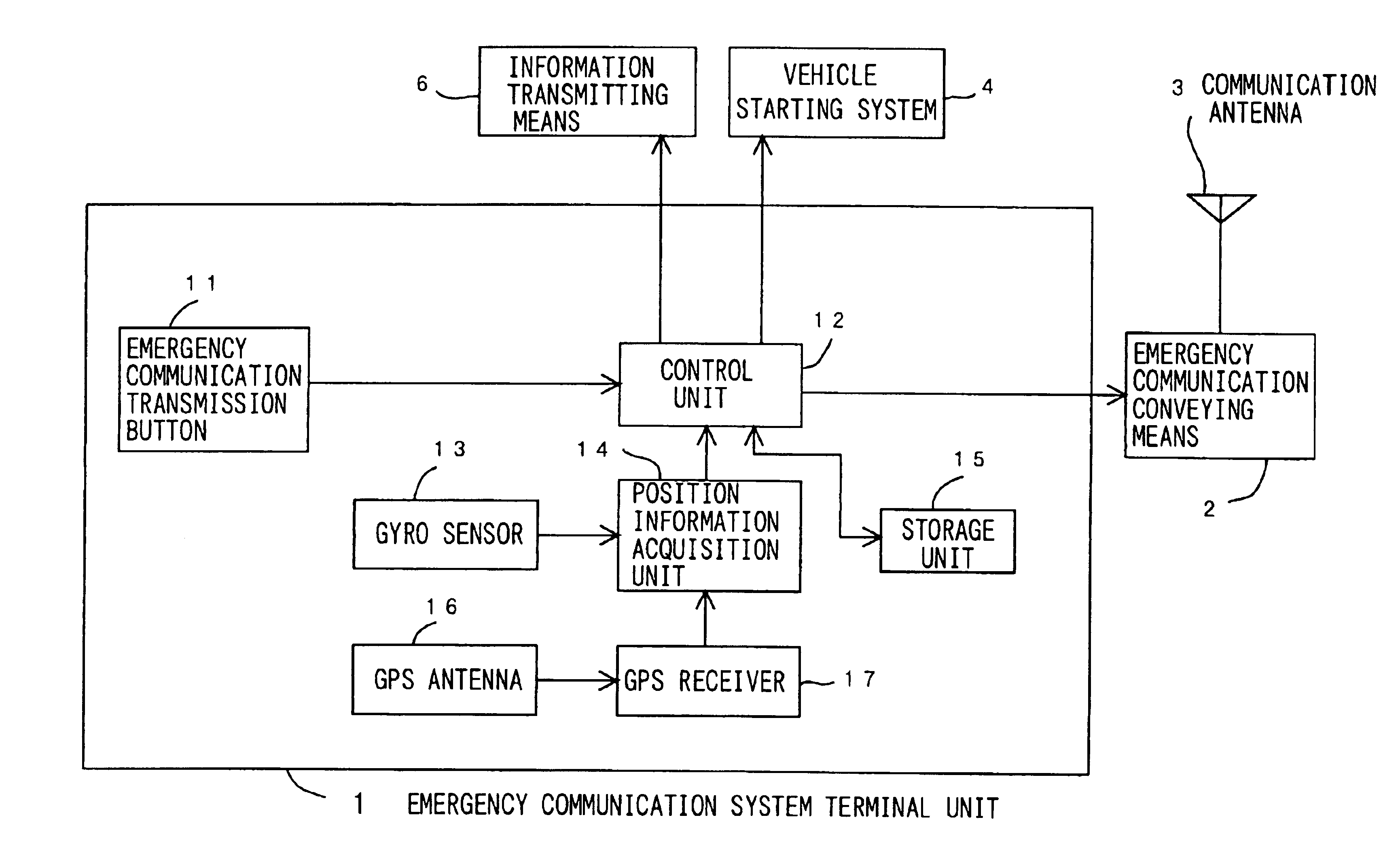
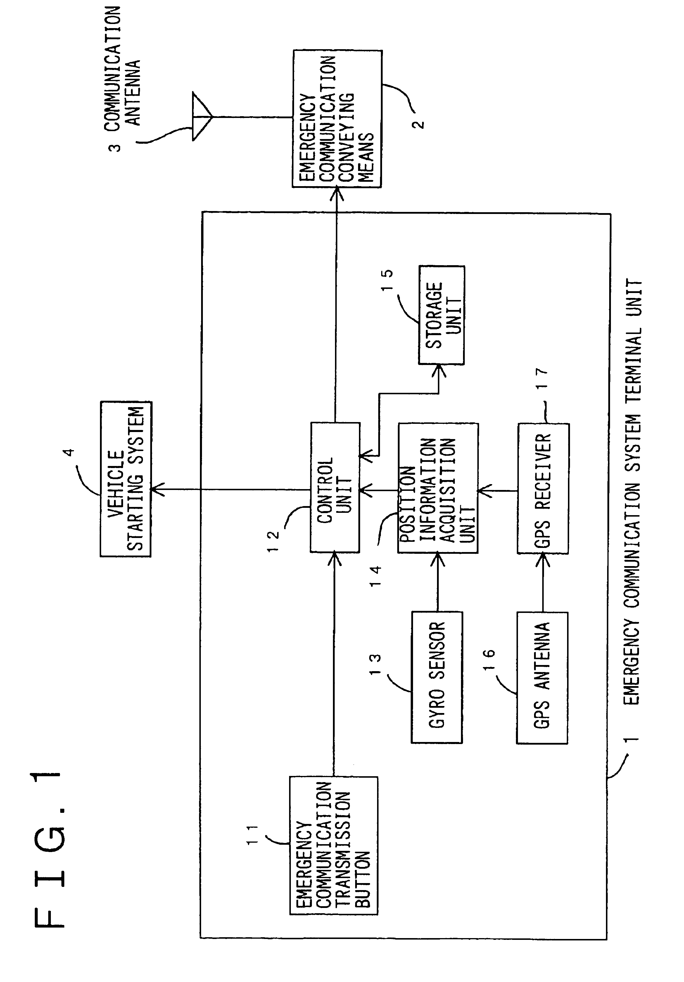
[0056]FIG. 1 is a block diagram of an arrangement of a first embodiment of an emergency communication system of the present invention. This first embodiment of the invention is used, for example, when requesting dispatch of a vehicle from police station or fire department in an emergency such as traffic accident, sudden illness, etc. Specifically, when an emergency situation such as traffic accident occurs to a vehicle, which is provided with an emergency communication system, the system of the present embodiment starts telephone transmission processing to a center, which controls the emergency communication system using conveying means 2 such as radio communication device. This first embodiment comprises an emergency communication system terminal unit 1, an emergency communication conveying means 2, a communication antenna 3, and a vehicle starting system 4. The emergency communication system terminal unit 1 is provided with the function to transmit the emergency comm...

embodiment 2

(Embodiment 2)

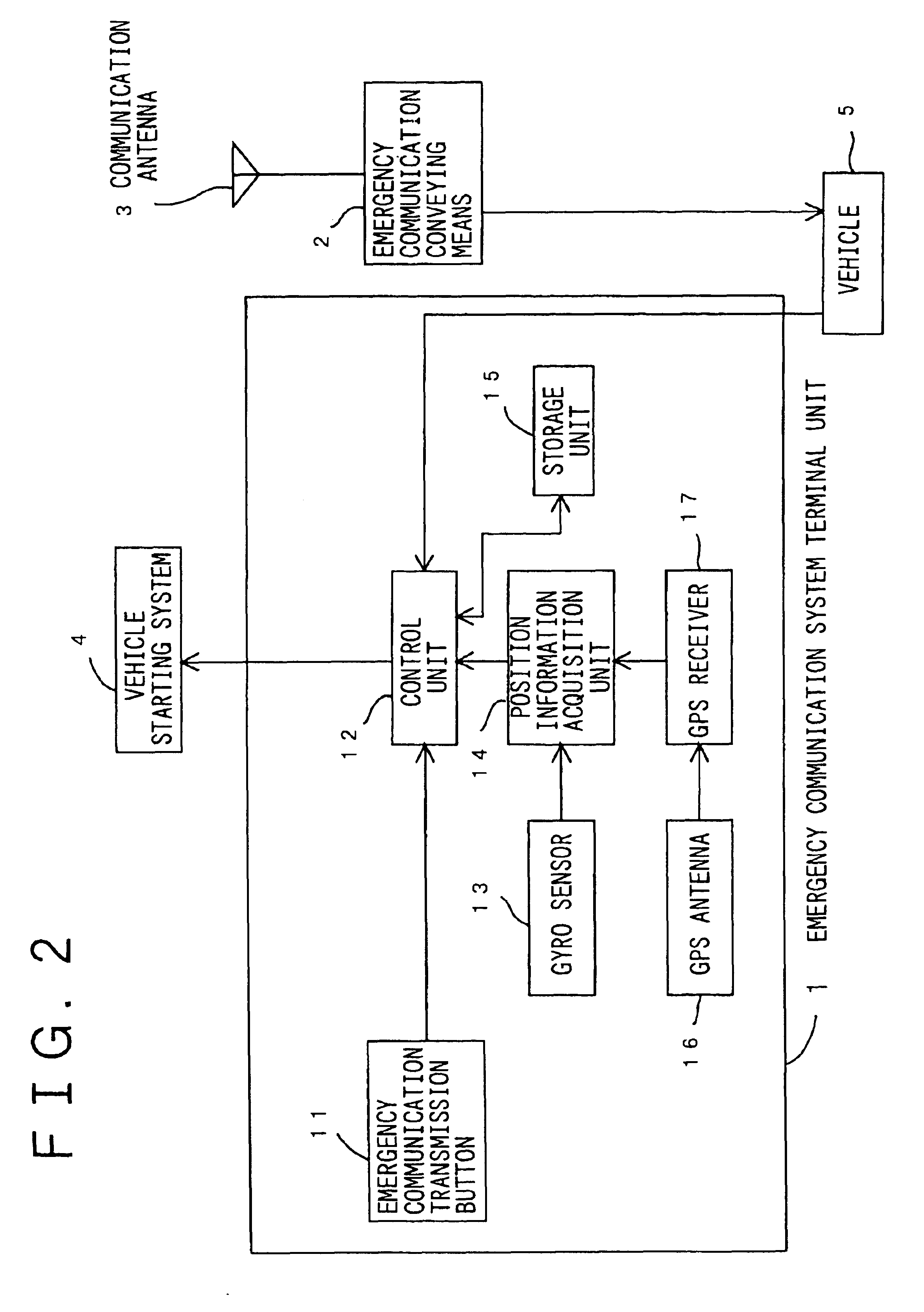
[0068]FIG. 2 is a block diagram showing an arrangement of an emergency communication system in a second embodiment of the present invention. In FIG. 2, the emergency communication system comprises an emergency communication system terminal unit 1, emergency communication conveying means 2 such as handy phone connected to the vehicle 5, a communication antenna 3, a vehicle starting system 4, and a vehicle 5 to be used as the transport means such as an automobile. Normal operation of the emergency communication conveying means 2 using means such as radio communication device adopted for the emergency communication system is confirmed, and by turning to enable status to start the vehicle, reliable operation of the emergency communication conveying means 2 is maintained while the vehicle is being driven.

[0069]The vehicle starting system 4 receives a status information, indicating that the emergency communication conveying means 2 is connected via the vehicle 5. When the em...

embodiment 3

(Embodiment 3)

[0070]Next, description will be given on an emergency communication system of the present invention in a third embodiment referring to FIG. 1. In FIG. 1, the emergency communication conveying means such as handy phone has an external interface (not shown). The emergency communication system terminal unit 1 provided with an external interface (not shown), to which the emergency communication conveying means 2 can be connected, is connected to the external interface (not shown) of the emergency communication conveying means 2. By performing communication using the same interface signal, it is possible to confirm that normal connection is achieved using the interface signal.

[0071]When it is confirmed using the interface signal that the emergency communication conveying means 2 is connected according to the status information indicating that it is connected, protection mechanism to prohibit the starting operation of the vehicle such as engine starting is turned off, and it...


PUM


Abstract

An emergency communication system is installed on a vehicle for transmitting emergency information such as traffic accident, sudden illness, etc. to a center such as police station. It is used for the purpose of preventing inadvertent neglect of the connection of a handy phone to the system terminal unit when the handy phone is used as the emergency communication conveying means. In case it is not connected normally, a signal is set to a vehicle starting system 4 to prohibit the starting operation of the vehicle. This information is displayed on LED or LCD on a dashboard of the vehicle by the information transmitting means 6, and it is further stored in a storage unit 15 so that it can be picked up from outside via an external equipment connection interface 7.

Description

TECHNICAL FIELD[0001]The present invention relates to an emergency communication system, and in particular, to an emergency communication system installed on a vehicle and used for transmitting emergency communication to police station, emergency communication center, etc. via radio communication.BACKGROUND ART[0002]Conventionally, an emergency communication system has been known, which can transmit data such as the present position of a vehicle, registered number of a vehicle, etc. to a center for controlling emergency communication system such as police station, emergency communication center, etc. These data are transmitted via emergency communication conveying means such as a handy phone installed on the vehicle in an emergency, e.g. traffic accident, sudden illness, etc. when a user is driving a vehicle.[0003]However, the conventional type emergency communication system uses a special-purpose radio device, e.g. a handy phone, as the emergency communication conveying means. For ...

Claims


Application Information

Patent Timeline
Patent Type & Authority Patents(United States)
IPC IPC(8): B60R25/04G08B25/00G08B29/00G08B21/00G08B23/00H04B7/26H04M11/04H04Q1/00B60R25/06B60R25/08B60R25/10B60R25/102B60R25/30G01C21/26G08B21/04G08B25/01G08G1/123H04W4/90H04W88/02
CPCH04M11/04B60R25/04B60R25/102G01C21/26G08B25/016G08G1/205
Inventor YOSHIOKA, KENJINAKAMA, YASUTOSHI
Owner PANASONIC CORP
Why Eureka
Try Eureka