Multi-channel video pump

Inactive Publication Date: 2005-10-11
ESCIENT +1
View PDF14 Cites 15 Cited by
  • Summary
  • Abstract
  • Description
  • Claims
  • Application Information

AI Technical Summary

Benefits of technology

[0014]It is an object of the present invention to provide a video streaming device that can output video signals at an average

Problems solved by technology

An MPEG data stream cannot be as easily sent using an asynchronous transmission system or network like Ethernet or Asynchronous Transfer Mode (ATM), because such asynchronous networks operate on the packet (or cell) level rather than the bit level.
Due to the use of packets to transmit data, it is more difficult to recover the input bit rate for a data stream from a network like Ethernet or ATM than from a multiplexed serial signal sent at a similar rate.
At one of the higher MPEG data rates of 6 megabits/second and assuming thirty frames per second with an average frame size of 200,000 bits, this granularit

Method used


Image

  • Multi-channel video pump
  • Multi-channel video pump
  • Multi-channel video pump

Examples


Embodiment Construction

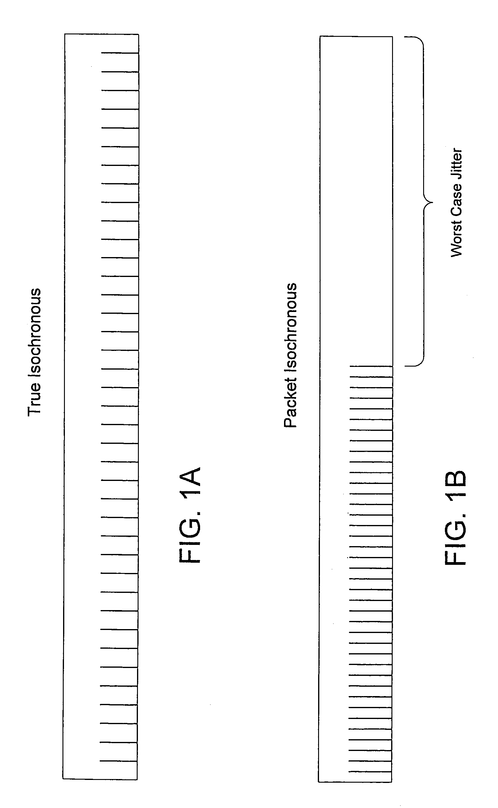
[0030]FIG. 1A illustrates the bit pattern desired for the MPEG stream (isochronous transmission). FIG. 1B illustrates the bit pattern for the same MPEG data stream as it is transmitted in a packet network, i.e., packet isochronous transmission. When the packet is released at precisely the correct time, as illustrated in FIGS. 1A and 1B, each bit after the first bit in each packet arrives early by an increasingly larger amount. The maximum early jitter occurs on the last bit of the packet. Ideally, the release of the next packet will be delayed, so that the first bit of the next packet will be received precisely “on time” by the receiving devices.

[0031]As should be apparent from the description of the related art above, the precise release point of a given packet will not have much effect on jitter as long as the magnitude of the error of actual release versus desired release is small compared to the jitter of the last bit caused by the difference between the network and stream bit r...


PUM


Abstract

A system for streaming a plurality of video or other recorded signals from storage to receiving devices maintains each of the signal streams at their encoded bit rate. The bit rate of each stream is detected from the stored signals and a corresponding queue is set up in memory or in a network interface card for outputting data at the detected bit rate. A channel timing module in the signal streaming device contains a two-stage dithered counter for each bit rate. The first stage of the counter counts one clock cycle longer than the second stage. By adjusting the ratio of the first stage and second stage counters in a fixed number of cycles (the dither cycle) a very precise average count is achieved. The average count is calculated to achieve the desired bit rate with a given packet size. Every time either the first stage of the second counter times out, a packet of data is sent to the corresponding queue in the network interface. As a result, the network interface is able to output packet isochronous signals with an average bit rate within one bit per second of desired bit rates between one megabit/second and 20 megabit/second and with a jitter of less than two milliseconds.

Description

CROSS-REFERENCE TO RELATED APPLICATION[0001]This application is related to U.S. Provisional Application Ser. No. 60 / 112,866, entitled Multi-Channel Video Pump, by Timothy W. Dygert, filed Dec. 18, 1998 and is a continuation-in-part of U.S. patent application Ser. No. 09 / 226,169 now U.S. Pat. No. 6,473,441, entitled Multi-Channel Video Pump, by Timothy W. Dygert, filed Jan. 7, 1999, both incorporated herein by reference.BACKGROUND OF THE INVENTION[0002]1. Field of the Invention[0003]The present invention is directed to streaming video signals and, more particularly, to an apparatus for simultaneously streaming user-specified video files encoded at varying bit rates over a single network.[0004]2. Description of the Related Art[0005]The role of streaming video in local area networks is expected to increase rapidly in the near future due to developments in video compression and deployment of transmission systems with increased bandwidth. Using the Moving Pictures Expert Group (MPEG) sta...

Claims


Application Information

Patent Timeline
IPC IPC(8): H04N5/00H04N21/234H04N21/238H04N21/643
CPCH04N21/23406H04N21/23805H04N21/64307
Inventor DYGERT, TIMOTHY W
Owner ESCIENT
Why Eureka
Try Eureka