
CDMA baseband receiver capable of establishing synchronization with peripheral base stations

a baseband receiver and synchronization technology, applied in the direction of synchronisation arrangement, high-level techniques, wireless communication, etc., can solve the problems of deteriorating precision, high search time, and inability to remove the correlation peak phase of known base stations including multi-path propagation components, etc., to achieve short time and high precision

Inactive Publication Date: 2005-10-11
NEC ELECTRONICS CORP
View PDF16 Cites 18 Cited by
  • Summary
  • Abstract
  • Description
  • Claims
  • Application Information

AI Technical Summary

Benefits of technology

[0022]Accordingly, the present invention is accomplished in view of the above-described circumstances, and an object of the present invention is to provide a CDMA baseband receiver capable of establishing synchronization with a peripheral base station with high precision in a short time at a peripheral cell searching operation in a CDMA communication system.

Problems solved by technology

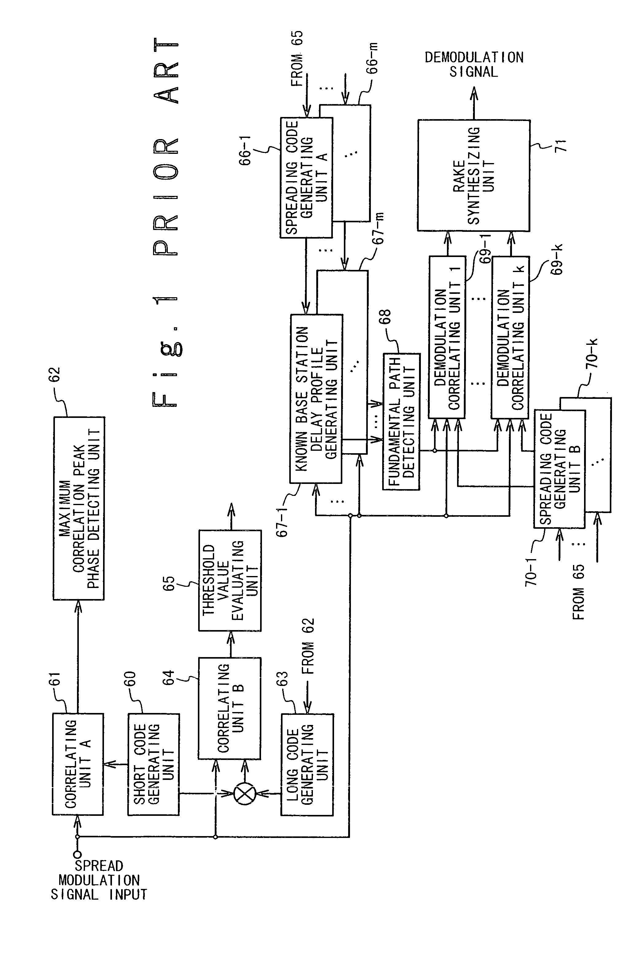
In the peripheral cell searching operation of the conventional CDMA baseband receiver, it is impossible to remove the correlation peak phase of the known base station including the multi-path propagation component.
As mentioned above, when the long code phase of the known base station is used to carry out the long code identification, not only precision is deteriorated in establishment of synchronization with a peripheral cell, but also a searching time is likely to increase.
In this case, even if an appropriate peripheral base station is present, it is impossible to establish the synchronization with the base station.
Therefore, when a vector summation of s( ) is calculated, the correlation is cancelled between the symbols so that high precision correlation detection cannot be carried out.

Method used


Image

  • CDMA baseband receiver capable of establishing synchronization with peripheral base stations
  • CDMA baseband receiver capable of establishing synchronization with peripheral base stations
  • CDMA baseband receiver capable of establishing synchronization with peripheral base stations

Examples


first embodiment

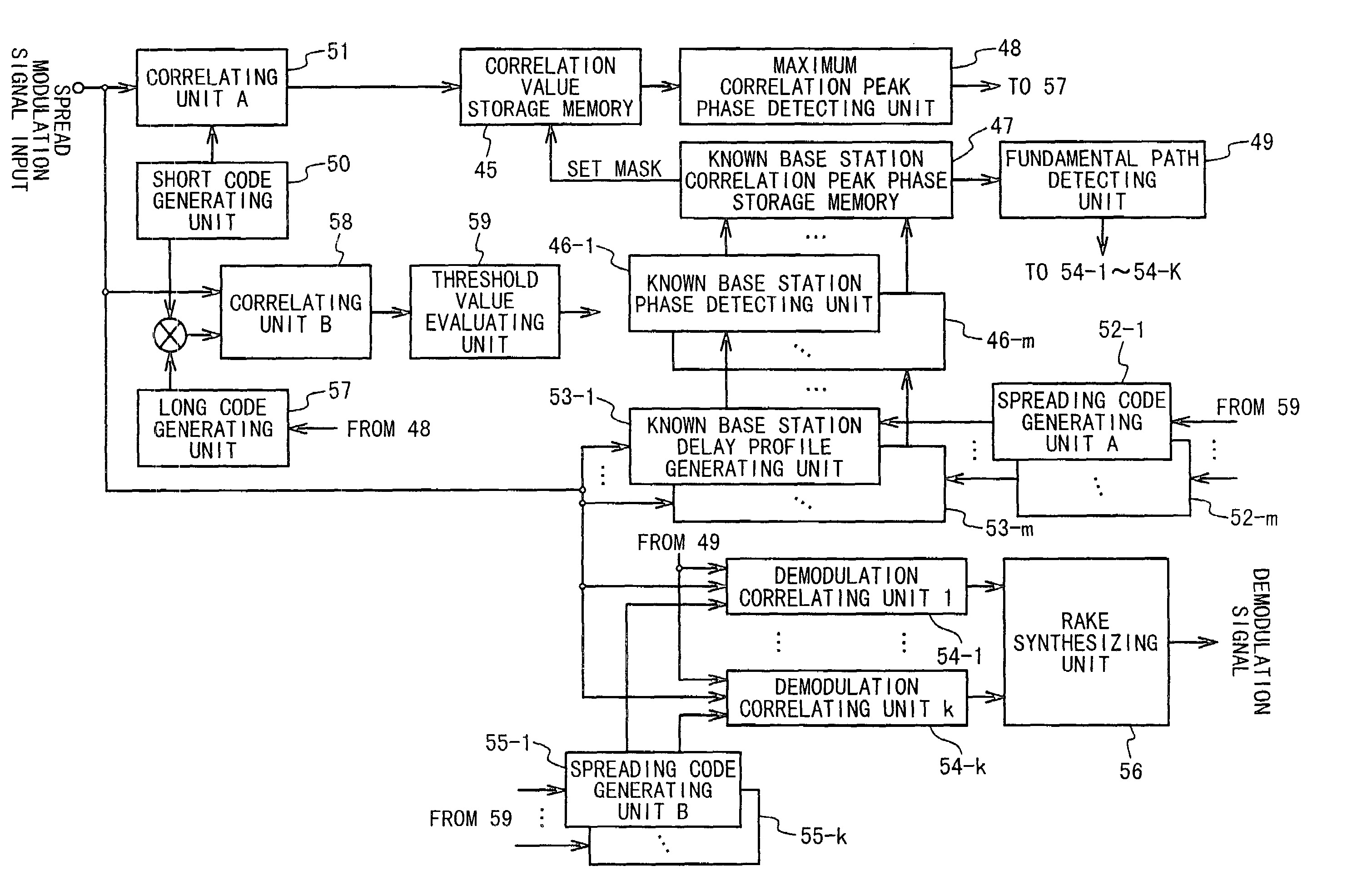
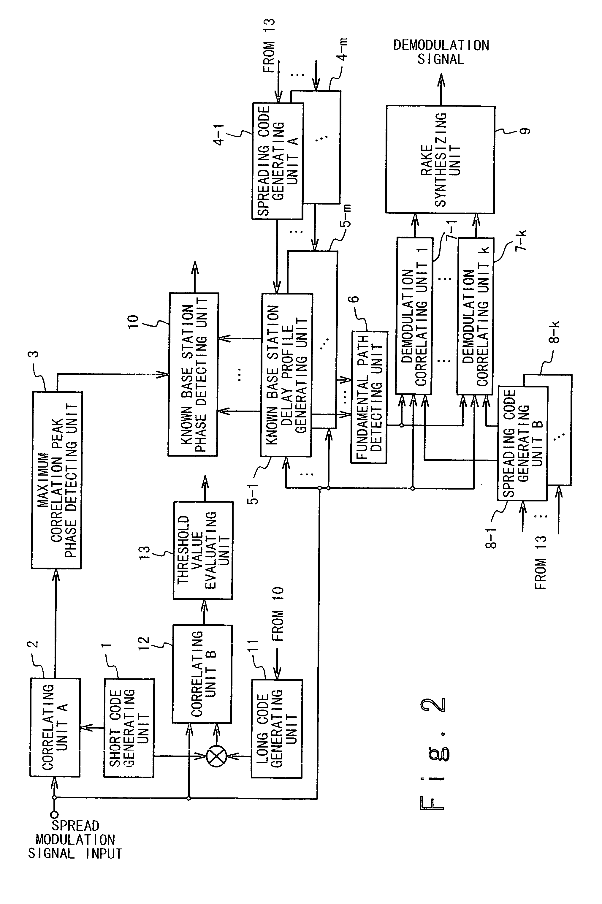
[0052]FIG. 2 is a block diagram showing the structure of a CDMA baseband receiver according to a first embodiment of the present invention. FIG. 3 is a block diagram showing a structural example of a maximum correlation peak phase detecting unit used in the first embodiment. FIG. 4 is a flowchart showing an example of the operation of the maximum correlation peak phase detecting unit used in the first embodiment. FIG. 5 is a view showing an example of the relationship between a long code mask symbol phase and a long code phase. FIG. 6 is a diagram for illustrating a delay profile generated by a known base station delay profile generating unit. FIG. 7 is a diagram showing an example of algorism of the known base station delay profile generating unit used in the first embodiment. FIGS. 8A and 8B are flowcharts showing the procedures of an initial process of synchronizing with a base station in the first embodiment when there is no base station in which synchronization has been establi...

second embodiment

[0095]FIG. 11 is a block diagram showing the structure of a CDMA baseband receiver according to a second embodiment of the present invention. FIG. 12 is a flowchart illustrating the processing of a known base station correlation peak phase detecting unit according to the second embodiment. FIGS. 13A and 13B are flowcharts illustrating the processing of a maximum correlation peak phase detecting unit used in the second embodiment. FIGS. 14A, 14B, and 14C are flowcharts illustrating the procedures of a peripheral cell searching operation carried out when synchronization with one or more base stations is established in the second embodiment.

[0096]As shown in FIG. 11, the CDMA baseband receiver of the second embodiment is mainly composed of known base station correlation peak phase detecting units 17-1 to 17-m, a known base station correlation peak phase storage memory 18, a maximum correlation peak phase detecting unit 19, a short code generating unit 20, a correlating unit A 21, sprea...

third embodiment

[0109]FIG. 15 is a block diagram showing the structure of a CDMA baseband receiver according to a third embodiment of the present invention.

[0110]As shown in FIG. 15, the CDMA baseband receiver of the third embodiment is mainly composed of known base station correlation peak phase detecting units 31-1 to 31-m, a known base station correlation peak phase storage memory 32, a maximum correlation peak phase detecting unit 33, a fundamental path detecting unit 34, a short code generating unit 35, a correlating unit A36, spreading code generating units A 37-1 to 37-m, known base station delay profile generating units 38-1 to 38-m, demodulation correlating units 39-1 to 39-k, spreading code generating units B 40-1 to 40-k, a RAKE synthesizing unit 41, a long code generating unit 42, a correlating unit B 43, and a threshold value evaluating unit 44.

[0111]Of these components, the short code generating units 35, the correlating unit A36, the spreading code generating units A 37-1 to 37-m, th...


PUM


Abstract

A CDMA baseband receiver includes a first correlating unit, a long code phase candidate outputting section and a long code determining section. The first correlating unit calculates first correlation values from a spread modulation signal and a short code which is common to base stations. The long code phase candidate outputting section outputs selected long code phase candidates corresponding to ones selected from the first correlation values, based on the spread modulation signal, and determined long codes. The selected long code phase candidates are other than long code phase candidates for known ones of the base stations. The long code determining section generates the determined long codes for unknown ones of the base stations from the spread modulation signal, the short code, and long codes generated based on the selected long code phase candidates. Each long code is peculiar to one base station.

Description

BACKGROUND OF THE INVENTION[0001]1. Field of the Invention[0002]The present invention relates to a code division multiple access (CDMA) baseband receiver capable of establishing synchronization with peripheral base stations in high precision at the time of a peripheral cell searching operation.[0003]2. Description of the Related Art[0004]In such an asynchronous DS-CDMA communication system, a plurality of base stations using a same frequency band are provided for cells adjacent to each other, respectively. When the base station communicates with a mobile station, the base station transmits a double-spread signal by use of a short code having a repetitive data symbol period and being common to the base stations, and a long code having a repetitive period longer than the repetitive data symbol period and being peculiar to the base station.[0005]In this case, when the mobile station present in a cell moves to the adjacent cell, and when the mobile station carries out simultaneous commu...

Claims


Application Information

Patent Timeline
Patent Type & Authority Patents(United States)
IPC IPC(8): H04B1/707H04B1/7083H04B7/26H04L7/00H04W56/00
CPCH04B1/70756H04B1/70775H04B1/7083H04B2201/70702Y02D30/70H04B1/709H04B1/7115
Inventor HASHIMOTO, TAKESHIMARUYAMA, YUICHI
Owner NEC ELECTRONICS CORP
Learn More